The example from the KBA How to use POP with lenslet arrays is using a lenslet array. It is defined with a user-defined surface us_array.c. So in this example, there is a pupil for the whole system so it won't trace a chief ray for a specific lenslet.
If you want to trace a chief ray for a specific lenslet, you can use vignetting factors. The vignetting factors can decenter and reshape the pupil. So you could set them up for a specific lenslet and that would then trace a chief ray for a specific lenslet.
I would recommend checking the help files about vignetting factors if you are not familiar with them.
Sandrine
Hi all,
In thinking out loud, I am imagining that Zhenfeng Zhuang is referring to a situation where you're creating a lenslet array in sequential mode using multi-configurations and coordinate breaks. In this case, let's say you have an array of 100 lenslets (i.e., you have a 10 x 10 array). So, you would have 100 configurations in the multi-configuration editor. Each configuration would specify an x and y decenter for a single lenslet. If you now place an aperture stop in front of the lenslet, then I'd imagine that you could aim the chief ray towards the stop by setting on the real ray aiming feature in the system explorer menu. However, I think I've done this before and found that OpticStudio sort of 'breaks down' for large angles. Maybe it works better if you have an imaging lens (say, a Cooke triplet or double Gauss) in front of the lenslet array, and the chief ray is aimed towards the real entrance pupil of the imaging lens. This would more or less model a more realistic situation where you have a camera lens and a lenslet array at the image plane. It would be interesting to see how this works out. Good luck! ~ Ronian
Thank you Ronian for your insight on this. Yes let us know how this goes and we'll be happy to help.
Hello Everybody,
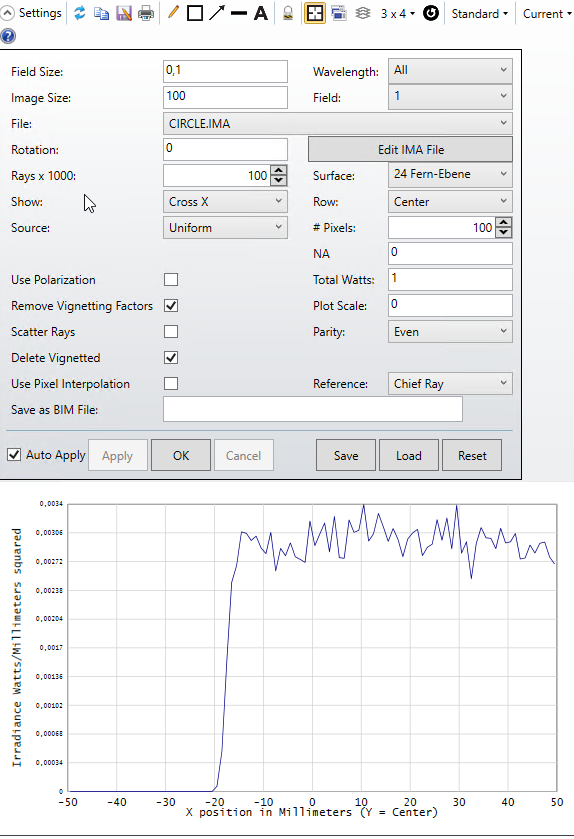
i am not sure if hier is the right place for my topic, but i take my chances. To analyse sensitivity of the decenter missalignment of a cylinderical MLA, which is useed to generate a uniform line, i use the Geometric Image Analysis as in attachment. The question is, what should be used as Reference (Chief Ray or Vertex) to analyse the beam decenter. only 125µm decenter of MLA causes about 16mm profile shift if i use the Chief Ray as Reference. In the 3D Layout but this decenter of beam profile is not the case.
Hi Atabak,
Thanks for your post here! Just to be clear here, so that I am sure that I understand your question correctly: are you asking about the proper Reference setting (either Chief Ray or Vertex) for your MLA decenter? Are both settings not quite giving you what you expect?
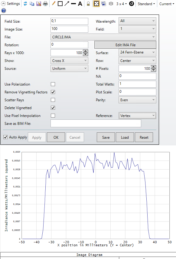
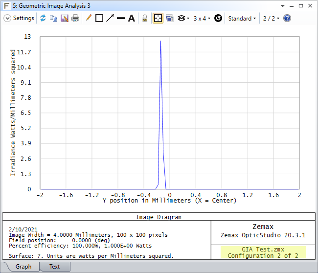
It's hard to say for sure without being able to look at your file, but is Surface 24 meant to be an evaluation plane rather than an optical surface? I noticed that when you set your Reference to Vertex, the beam itself looks well-centered on Surface 24. If this is a surface after your decentered cylindrical element, you should check to see if you have defined your coordinate-adjusting settings (whether it's through Coordinate Break surfaces or through the Surface Properties) to ensure that your surface after the decentered element is not moving as well (if that is what you're trying to model). For instance, in the below image, I have two configurations for a cylindrical lens, Config 1 (in blue rays) being the nominal placement, and Config 2 (in green rays) being a displaced len along the Y-axis:
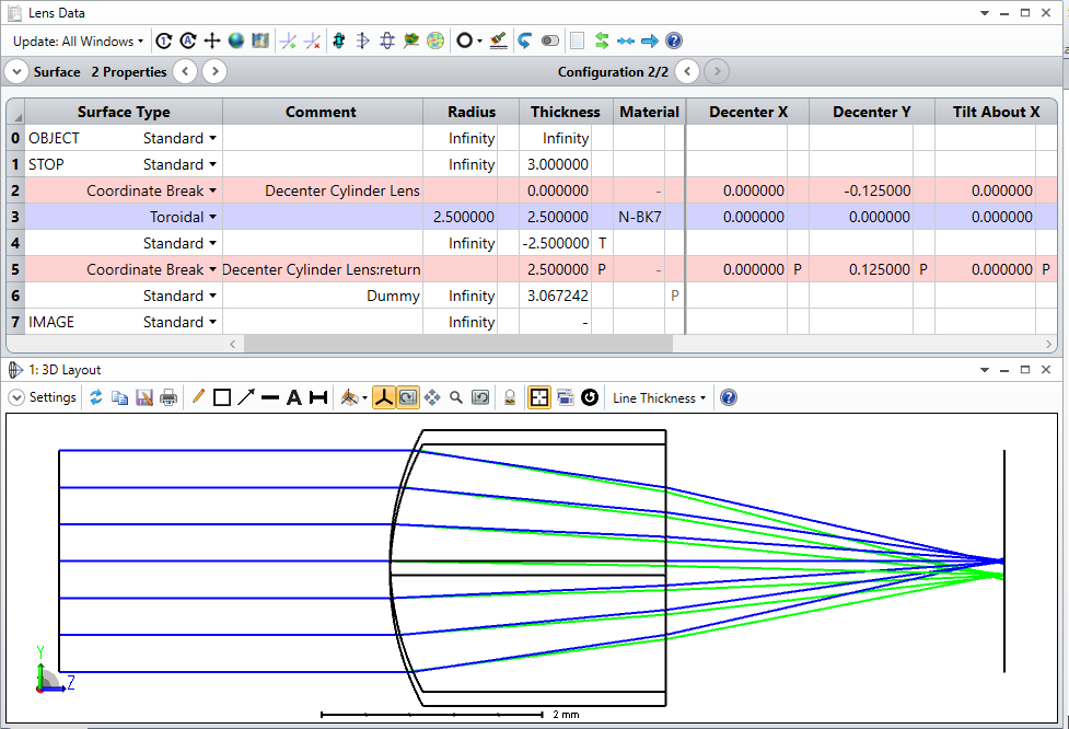
Since the decenter is defined to only apply to the lens, the image surface is left unaffected. Setting the Reference to Vertex then shows the displacement of the focused beam in a way that matches up with what we see in the 3D Viewer:
If this doesn't answer your question, though, we may be able to provide more help if we can take a look at your file. If you can, feel free to share it on this thread here. Otherwise, you are welcome to open a support case on MyZemax at this link.
~ Angel
Hi Angel,
thanks for your quick reply. I created a dummy version of my design to upload hier. I used both coordinate brake and decenter in non-seq-editor to move the MLA about half pitch size prependicular to beam propagation. I got the same results from both ways. Just to be clear: GIA with reference to Chief Ray has too much shift in compare to GIA with refrence to vertex. unfortunatly i can not explain it with the optical design fundamental of MLAs.
Atabak
Hi Atabak
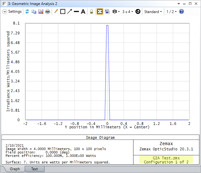
I followed your description and added a pair of CB around the non-sequential component surface. I created 2 configs: a nominal and a decentered one.
The issue is that in one case the chief ray can't be traced:
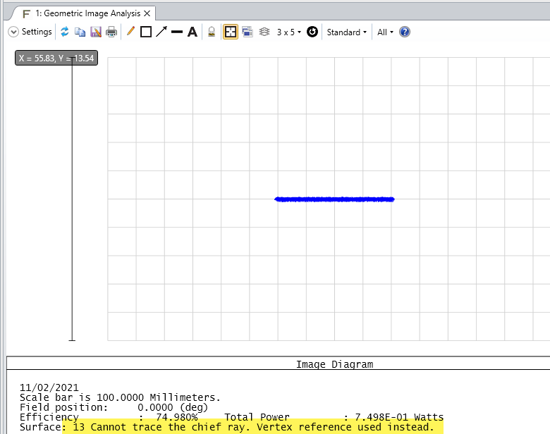
So that means that the reference is the same in both configs.
Sandrine


