Solved

Tilted image plane

  • 12 October 2021
  • 7 replies
  • 489 views

Dear Sir/ Mam,

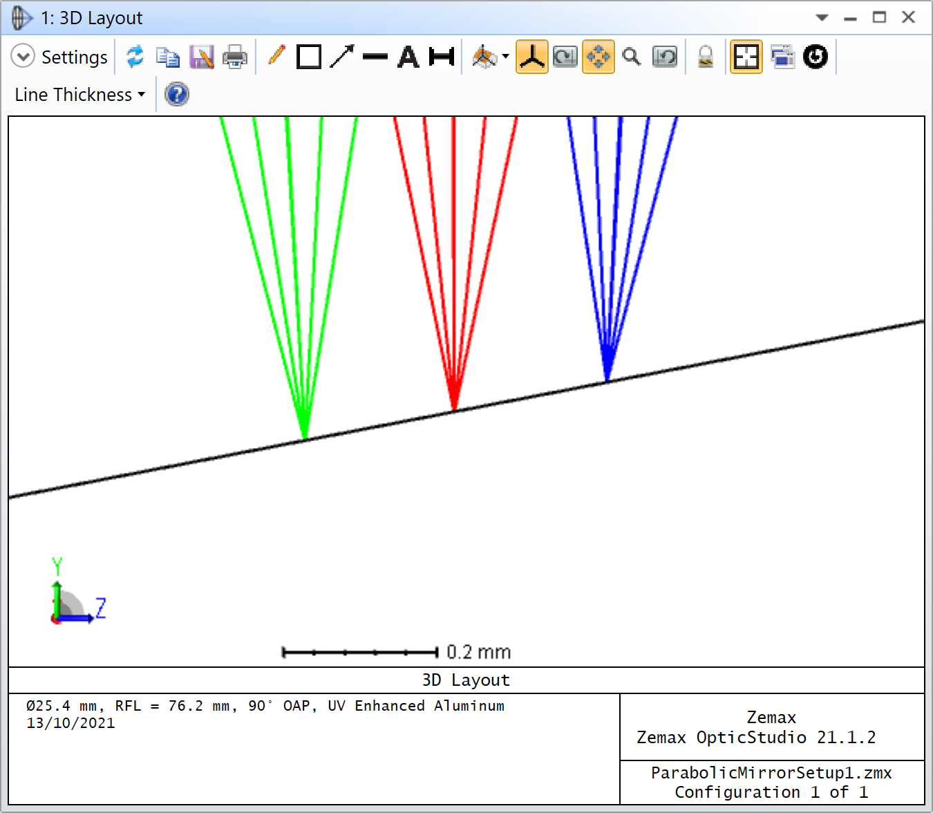
I have been using single Off axis mirror with a paraxial lens. There is a lilt in image is expected.

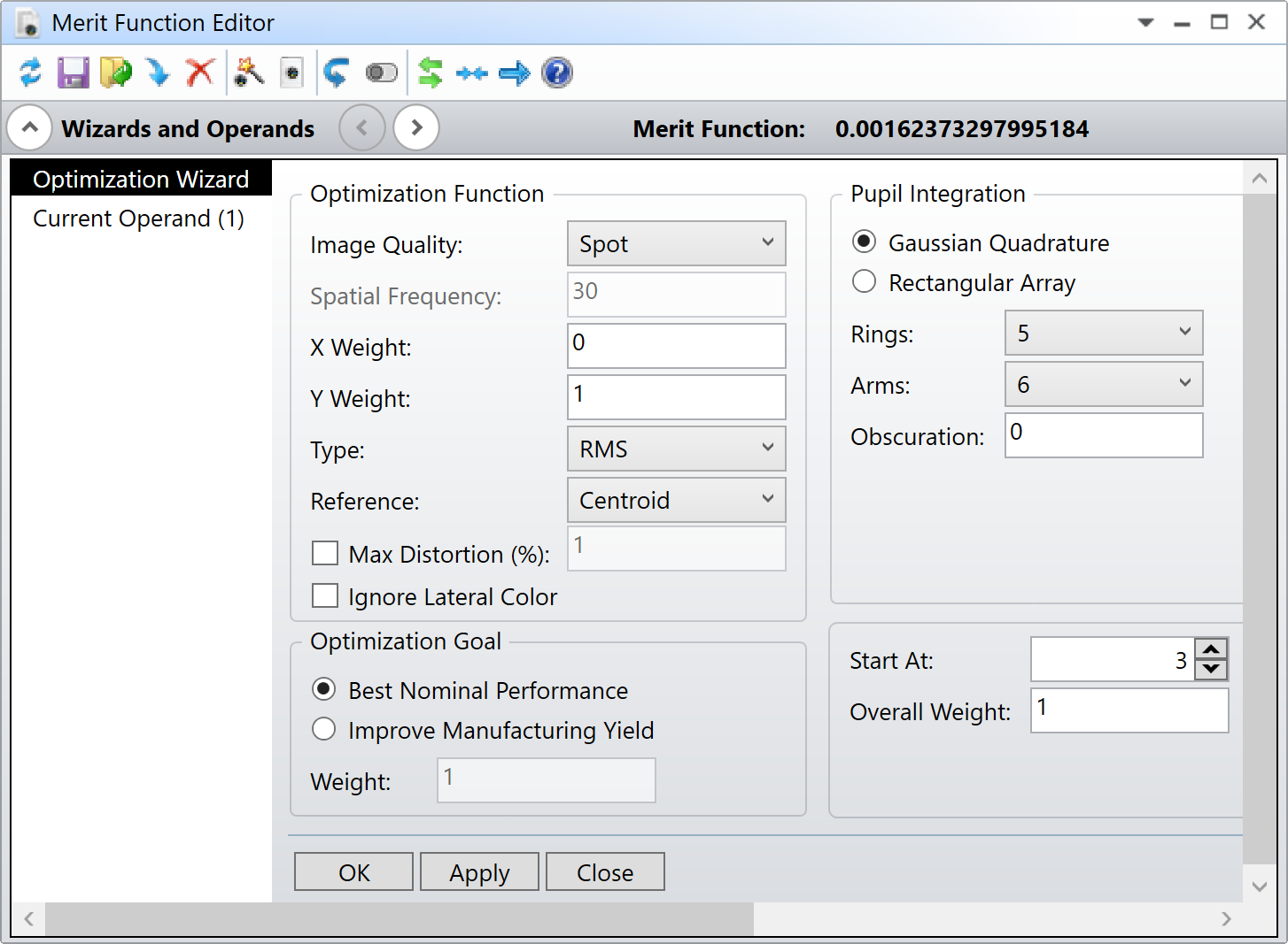
To know the tilt in a 3D space I used coordinate break.  I can see the tilt in x and y with chief ray solve.

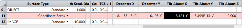
  1. Is it correct to assume the tilt angle is correct with respect to image plane in an off axis system?
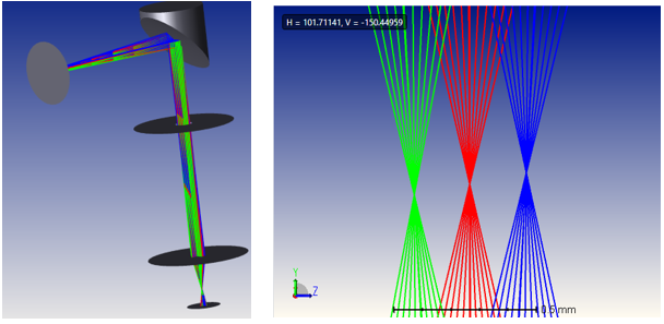
  2. Why the image plane is drawn is not as expected?
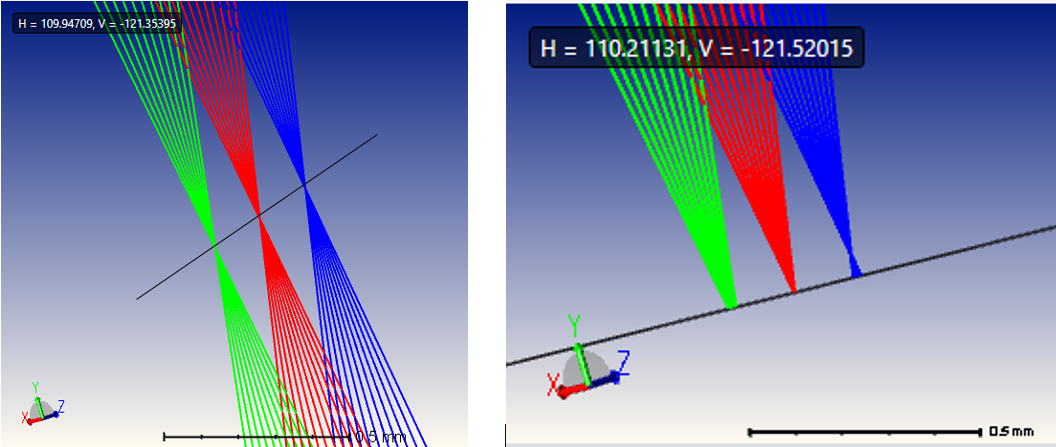
  3. Expected image plane vs  actual drawn image plane
  4. How can I check tilt in z axis?


Regards

Komal Thakur

icon

Best answer by David.Nguyen 13 October 2021, 18:17

View original

7 replies

Userlevel 7
Badge +2

Hi Komal,


I’m not sure this explains your problem but when you use the Chief Ray Solve on the Coordinate Break, you obtain a plane orthogonal to the chief ray. Remaining aberrations could still cause your fields to be out-of-focus with respect to the Coordinage Break plane (I’m assuming the colors in your screenshots are fields, and not wavelength...).

I think it would be helpful if you could share this file with us, and describe what tilt you expect along Z.

Take care,


David

Userlevel 6
Badge +4

I think David is right about this. The correct tilt can be determined by making the tilt variable. If optimization is done with a spot radius merit function that ignores lateral color, then the tilt will be optimized for an image plane that reduces each of the spots.

Dear All,

 @David.Nguyen  Thank you for explanation. (yes the color are field)

@David David Thank you for suggestion.

Please find attached file and help me to determine the how much is the tilt in image plane?


Regards

Komal Thakur

Userlevel 7
Badge +2

Dear Komal,


Thank you for sharing your file. I had a quick look at it, and I think you have an additional issue that would prevent you from optimizing the spot radius like @David rightly suggested. The issue I came across was astigmatism. In short, by tilting to find the plane you were looking for, the spot was spreading in the orthogonal direction. Therefore, I used the Spot Image Quality, with a X Weight of zero (as shown below) thus only measuring the spot size along the Y direction.

It gives the result below:

And an angle of +10.898 degrees about X. I’m attaching your file to my reply. Let me know if that is kind of what you were expecting.

Take care,


David

Userlevel 6
Badge +4

Yes! That had slipped my mind. The spectrometers I’ve had experience with have all targeted either a slit (monochromators) or striped detectors. The spots need to be narrow in only one dimension. 

Userlevel 7
Badge +2

Yes! That had slipped my mind. The spectrometers I’ve had experience with have all targeted either a slit (monochromators) or striped detectors. The spots need to be narrow in only one dimension. 

Oh I see, this is done on purpose then, nothing to do with astigmatism.

Thanks a lot @David !

Take care,


David

Dear All,

 In this case, ( OAPM with paraxial lens) astigmatism is expected.

@David.Nguyen Thank you very much, I learned something new.

@David Thanks for introducing the spectrometer application.  So, astigmatism does not affect spectroscopy?  


Regards

Komal Thakur

Reply