I made a stellar interferometer using NSC model, but the change of baseline didn't get different interference fringes ,which should not happen .
I couldn’t figure out why.

I made a stellar interferometer using NSC model, but the change of baseline didn't get different interference fringes ,which should not happen .
I couldn’t figure out why.
Best answer by Jeff.Wilde
The stellar interferometer assumes the object is a star of finite diameter radiating spatially incoherent light. Light from each point on the star can interfere with itself, but not with light from other points. The interferometer therefore forms a superposition of numerous interference patterns, one fringe pattern from each point (or small spatial patch) on the star. These individual fringe patterns are similar in modulation depth, but they vary in relative phase depending on the lateral position of the corresponding source point (on the star) as well as the baseline separation. The result is that as the baseline increases, the incoherent sum of these fringe patterns causes the net fringe modulation depth to decrease. In other words, as the baseline increases the elemental fringes combine to “wash-out” the observed fringe. Some simple math allows one to find the diameter of the star from the baseline separation at which the observed fringe modulation depth goes to zero.
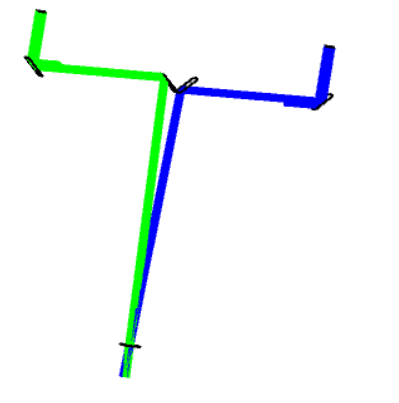
So, with this physics in mind, modeling of the stellar interferometer requires modeling the elemental fringe patterns from *many* pairs of incoming beams (one pair shown in the layout as the blue beam + the green beam). For each pair of beams, the relative phase between the two individual beams must be set as if the light emanated from a given point on the star. One way of doing this in OpticStudio is to apply the correct “Initial Phase” to one of the two source in the model to create the appropriate fringe phase shift:

The star can be approximated by a discrete set of mutually incoherent point sources. Modeling incoming light from across the entire star diameter then requires looping through several slightly different configurations (one for each point source), recording the elemental interference pattern for each configuration, and then incoherently combining them all to get the final result for a single baseline separation. Then, the baseline can be changed and this process repeated. So, it is doable, but is best accomplished using a macro to automate the process.
As noted by M. Mansuripur, “The essential idea behind the stellar interferometer is that of a double-slit inteferometer, ...” (see, Classical Optics and its Applications, 2nd Ed., Ch. 35, “Michelson’s Stellar Interferometer”). Here is a link to a Knowledgebase article that discusses how to construct an NSC model of a double-slit interfereometer when using an extended incoherent source: Simulation of Young's interference experiment via geometric ray tracing in OpticStudio. A modified version could be used to mimic a stellar interferometer.
Enter your E-mail address. We'll send you an e-mail with instructions to reset your password.
Do not provide any information or data that is restricted by applicable law, including by the People’s Republic of China’s Cybersecurity and Data Security Laws ( e.g., Important Data, National Core Data, etc.).
不要提供任何受适用法律,包括中华人民共和国的网络安全和数据安全法限制的信息或数据(如重要数据、国家核心数据等)。
