I have couple of questions regarding “Source Diode” setup.
1: There is a column “ X - divergence, Y - divergance” in this column either we have to enter half of the full divergence angle or full divergence angle? That is, if laser diode is having 33 degree full divengence in y direction so in “Y-Divegence” column what we have to put, 33 degree or 16.5 degree?
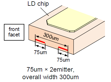
2: Similarly we have column for “Delta X” and “Delta Y”, in this column we have to put center to center spacing of the emitters or edge to edge spacing.
According to above layout in “Delta X” column we have to put 150um or 225um?
Regards,
Chandan Maurya
Best answer by David
Hi Chandan,
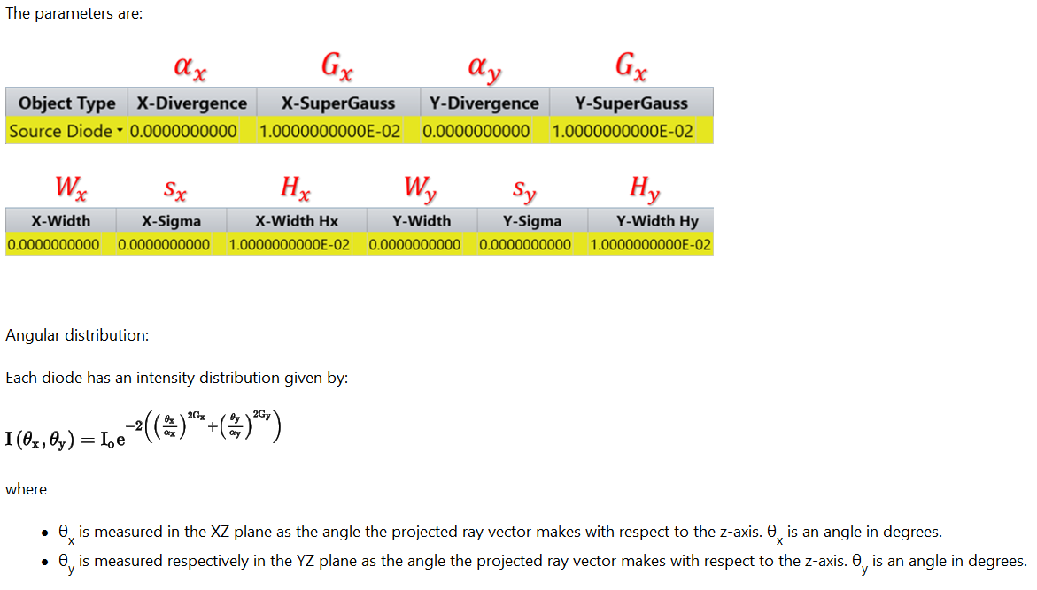
X-Divergence and Y-Divergence are not strictly the beam divergence angles. They are parameters of a Gaussian or super Gaussian distribution. The distribution is Gaussian if the SuperGauss value is 1. In this case, the divergence values are the angles in degrees at which the Gaussian beam intensity falls to 1/e^2 of its maximum intensity on the respective axis. So this is a half angle. From the help file on Source Diode:
The help entry has information relating these parameters to FWHM beam divergence.
It appears to me that what you wish to model is a pair of laser diodes on one die. The separation of the two diodes appears to be 225 um center-to-center. This is the delta-x value if number of diodes in the array is given as 2 in the x dimension and 1 in the y dimension, as above.
Dear David,
Thanks for your reply.
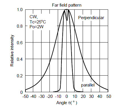
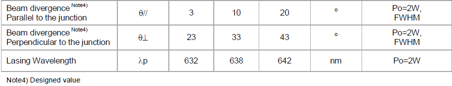
I am attaching the emission pattern of laser diode that I want to simulate…
Fig: Far field pattern of laser diode
As far as I understood based on the above discussion, I have to enter 33 degree in “X - divergence” if I am cosidering x direction as gaussian divergence perpendicular to the junction. Am I right?
From the graph it appears that 33 degrees is the 1/e^2 half angle, if so then that is correct. I assume that is the 33 entered in the table, but the table as shown does not have column labels.
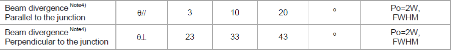
Also, there is something misleading in my answer above. The divergence parameters give the 1/e^2 angle in degrees regardless of the values of the super-Gaussian (Gx, Gy). However, the formula for FWHM given in the help entry would change for values of Gx, Gy other than 1.
Thanks, Chandon. I still remain a bit uncertain. From the graph it appears 33 degrees is the 1/e^2 half angle. But in the table I see a test condition of FWHM. Does the spec say clearly how the 33 degrees is measured?