Solved

Simulating the spot size of a focused fiber output

  • 26 June 2021
  • 5 replies
  • 1393 views

I'm working on a system where a beam is launched from a multi-mode fibre (having a certain core diameter and NA), goes through a series of lenses, and is then focused on the image surface.


What would be the best way to simulate such a source in sequential mode? What would be the best way to find the resultant spot size on the image surface?

icon

Best answer by David 26 June 2021, 02:22

View original

5 replies

Userlevel 6
Badge +4

Hello Ryan,


In sequential mode I would model the output of the fiber as an object with fields set to object height, The maximum field should be equal to the radius of the fiber. The system aperture shoud be set to object space NA with the NA value matching the fiber. Checking telecentric object space will let the fiber act as a source rather than allowing OpticStudio to target the stop. These settings will allow optimization for image quality across the fiber diameter.


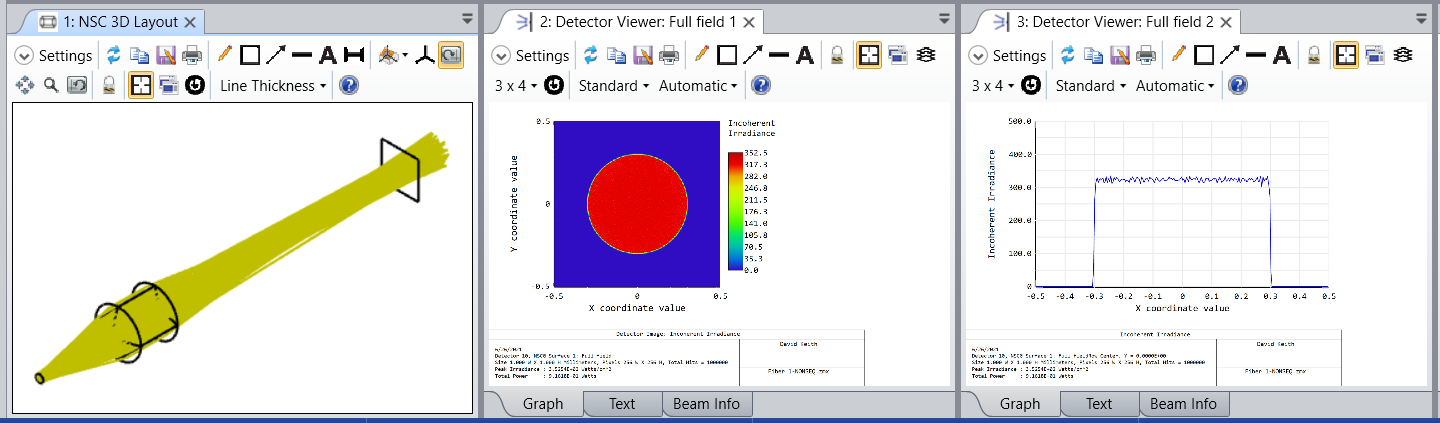
To simulate the resulting image in sequential mode, I would use Geometric Image Analysis. One of the source files that comes with OS is circle.ima. That is a disk filling a square field. If you then set field size equal to the diameter of the fiber you will be imaging a disk emission of the modeled NA. This provides a qualitative output (or perhaps semi-quantitative). For a quantitative simulation I use non-sequential mode. It's worth noting that neither of these methods simulate diffraction effects  


The attached file is an example. It implements the design of a 200um NA 0.22 fiber output being imaged with a magnification of 3x. A singlet with one aspheric surface and one spherical surface is diffraction limited at 550nm.


Kind regards,


David

Userlevel 6
Badge +4

And here I attach one more file.


I converted Fiber 1 to non-sequential using the Convert to NSC Group tool. (I first made the clear semi-diameter of surface 1 equal to it's mechanical semi-diameter, just to remove the flat.) The conversion produces a non-sequential version with source-detector pairs for each field. Here we want to simulate the imaging of the fiber, so I added a Source Two Angle to represent the fiber and a detector large enough to contain the full image. The source has a diameter the same as the fiber and a 12.7 degree half angle to match the 0.22 NA. It's spatial and angular shapes are set to elliptical. The source and detector were each were positioned using the pre-existing components as reference objects.


A ray trace with splitting on shows an efficiency of 0.916 to the image plane. The losses are due to Fresnel reflections and could be reduced with AR coatings, which we could model as well.


Kind regards,


David

Badge +1

Hello David, 


Since the fiber has a different spatial distribution,near field top hat and far field  type of gaussian disterbution I would use with source elipse 


does my way correctly describe the situation? 


Yair 

Userlevel 6
Badge +4

Hi Yair,


A single mode fiber certainly has a Gaussian far field, since that is a characteristic of the one mode the fiber supports. But in my experience the output of a multimode fiber is dependent on the launch conditions. I can't say I know a lot about this, but I have had experience working with the data from a specific set of experiments. In this case, the input to the fiber was a cone of light focused to a spot at the center of the core. The spot was smaller than the core diameter and the half-angle of the cone less than the acceptance angle of the fiber. So launch rays were meridional rays (no skew rays), and the fiber was under-filled.


The far field of the fiber output was well modeled as a top hat distribution convolved with a Gaussian, with the Gaussian width a small fraction of the width of the top hat. The 50% threshold of the edges corresponded to the launch cone angle. Like this:


Perhaps it's the case that for a sufficient length of cable the output would be Gaussian. I think that you've done a lot of work with fiber. I would be interested in your thoughts on this.


Kind regards,


David

Badge +1

Hi Davud,


I think your way reflects the situation in case of multi mode fiber , in the result seems that getting a beam on a high M^2 i would be interesting to know what the quality of the beam in far field  becuse It is important for us to evaluate after the passage of light in the fiber how much quality is damaged , as we know the half beam div at far feild and beam dia we can calculate the  M^2..


best 


yair 


Reply