How to define Led light source and light from it is carried by fiber optic cable to the optical system in the lens data editor. (The end of the fiber optic cable is a circular plane surface.)

Solved
Simulating optical illumination system.
Best answer by David
Hello Suguna,
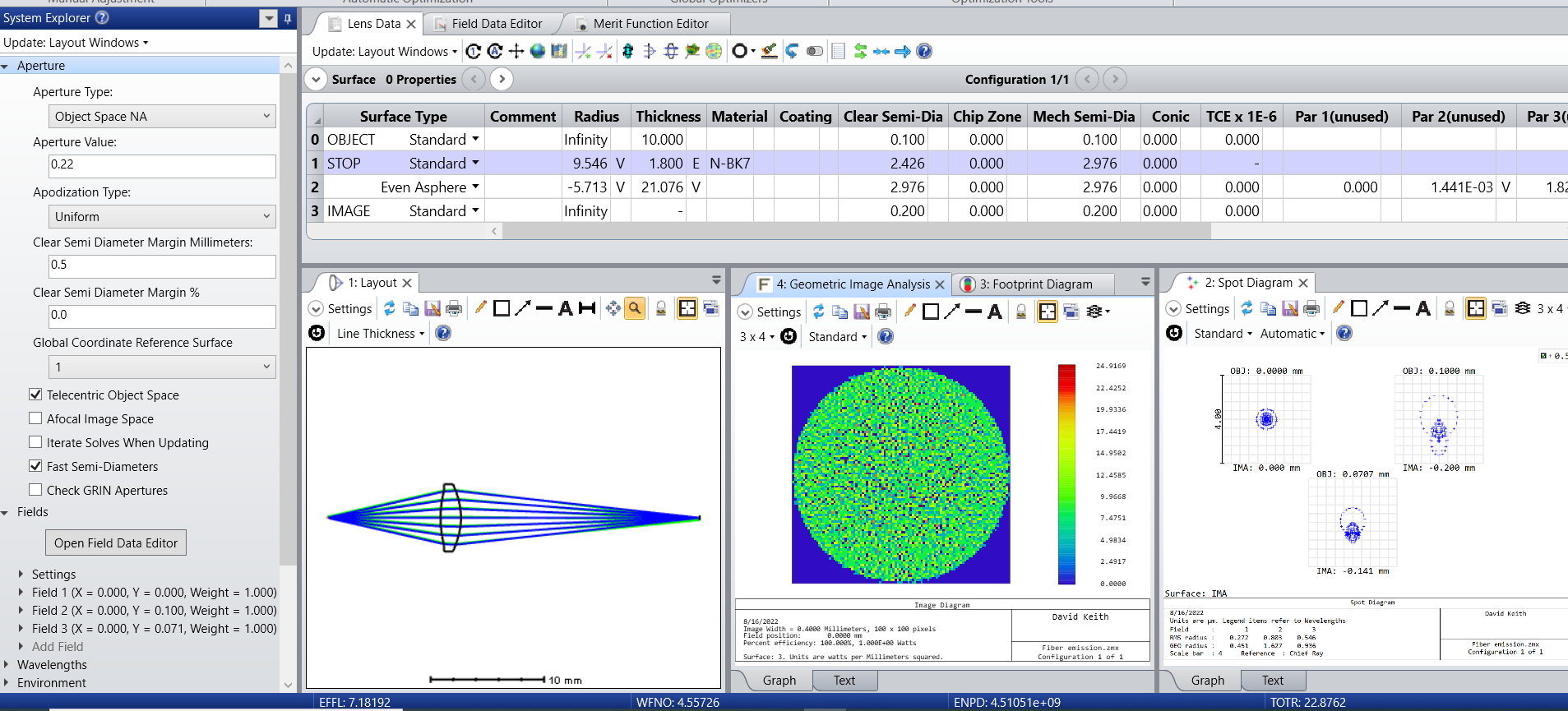
Since you refer to the Lens Data Editor I assume you are working in sequential mode and designing optics to receive and process light emitted from the fiber end.
For short fibers, the spatial and angular distribution of emitted light can depend on the launch conditions. However, for fibers where the launch conditions are spatial and angular overfill, or for long fibers, it is reasonable to assume the emission is uniform over the face of the fiber with an angular distribution defined by the NA of the fiber.
In the attached example I assume a multimode fiber with a 200um core diameter and an NA of 0.22. For optical design purposes the fiber emission is modeled as three field points, the extreme field being 100um to coincide with the edge of the fiber. The aperture is set to Object Space NA = 0.22. The Telecentric Object Space box is checked so the the modeled rays are directed parallel to the fiber axis rather than being directed toward the stop.
For the sake of this example, the goal is to collect the light at a distance of 10mm and focus it to an image with 2x magnification with a single lens.
The Optimization Wizard was used to produce a merit function, with user operand PMAG added to enforce the magnification. The lens was optimized for spot size, using radii on both surface and the last surface aspheric. The spot diagram looks good.
The design is further evaluated using Geometric Image Analysis. The analysis uses the provided CIRCLE.IMA file. (It’s really a disk.) The (full) Field Size is set to 0.2 to model the fiber diameter. The Image Size is set to 0.4, in the expectation that the magnified fiber face will exactly fill the GIA image field.
This is a typical way to design optical systems to process illumination sources. It is also typical that the designs are converted to non-sequential mode for quantitative analysis. (Simple designs can be done in non-sequential without starting first in sequential.)
I attach a ZAR file enclosed in a zip.

Enter your E-mail address. We'll send you an e-mail with instructions to reset your password.
Need more help?
To Chinese users:
Do not provide any information or data that is restricted by applicable law, including by the People’s Republic of China’s Cybersecurity and Data Security Laws ( e.g., Important Data, National Core Data, etc.).
不要提供任何受适用法律,包括中华人民共和国的网络安全和数据安全法限制的信息或数据(如重要数据、国家核心数据等)。