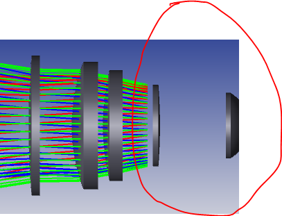
I have a system view of shaded model, however my shaded model viewer has some missing rays starting from a certain distance as shown on the picture below with a red indicaiton.
What might be the possible reasons? Any help/comment is appreciated.
Thank you in advance.
Best answer by David
Hi Onder,
It’s also possible that the ring of marginal rays it being clipped by the stop. This could happen if Ray aiming is set to paraxial but the paraxial estimate sends the marginal rays just outside the stop. If so, a fan will will show most rays getting through and setting ray aiming to real will solve the problem for the ring.
As far as I noticed the reason for unseen ray tracing is all about aperture stop definition. Despite the current definition of my aperture stop, on my spot diagram my rays were landed producing spot distribution. This situation fairly decieved me. If the aperture stop cuts my rays out , I am curios about why I contue to see the rest of the ray tracing. If I am not clear enough, I can try to illustrate more
Is it possible the layout shows a ring of rays that actually misses the next surface and is terminated, while the spot diagrams use a ray pattern that fills the stop?
Thank you for your response. It is sequential mode. I would like to share the file but it was a .zmx file at the very beginning of my working phase of my early hours yesterday. This picture belongs to my .zmx file but it changed quite much that it is completly changed at all. On the cross section view the rays were visible but the clear thing I noticed that when I editted my stop settings, the initial missing rays became visible landing on my image plane in shaded view as well. I am sorry not to save the initial state of my file of which I shared the screen shot.
I would like to contribute more of these I wrote above.
Is it possible the layout shows a ring of rays that actually misses the next surface and is terminated, while the spot diagrams use a ray pattern that fills the stop?
Kind regards,
another David :-)
Hi David the rays that terminates in the picture is exactly at the stop surface, due to the ZOS view angle the stop is not seen, it is just side view of the stop surface that is why it is invisible from this perspective.
It’s also possible that the ring of marginal rays it being clipped by the stop. This could happen if Ray aiming is set to paraxial but the paraxial estimate sends the marginal rays just outside the stop. If so, a fan will will show most rays getting through and setting ray aiming to real will solve the problem for the ring.
Try changing the ray pattern. This issue will not occur when you choose X-Y Fan as ray pattern, it occurs only with ring configuration as @David mentioned above.