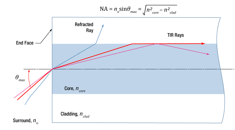
I am trying to simulated the fiber with NA 0.22. For this I have taken Core RI 1.49 and claculated the cladding RI for desired NA, it is coming 1.473. I have used the formula NA = sqrt(core_RI^2 - cladding_RI^2).
I am using “cylindrical volume” to simulate the fiber in non-sequential mode. Is this the right approach to have a fiber with desired NA in Zemax? Doubting because…...
When I changed the NA of fiber to 0.5(core RI 1.45 - cladding RI 1.3610), just to check wheater coupling efficiency is changing or not. I am getting same power at detector, placed at front surface of fiber! and hence same Coupling efficiency.
I am attaching the zemax file of my Simulation for your reference.
A comment would be appreciated.
Thankyou.
Best answer by Jeff.Wilde
Yes, the NA of a step-index MMF is dictated by the core and cladding refractive indices:
In my examples I kept the fiber NA fixed at 0.22, and considered coupling for two different launch beam NA values (0.20 and 0.30).
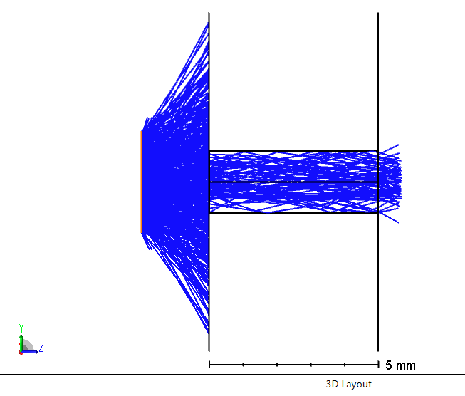
In your model the light hitting the fiber entrance face is overfilling the fiber both spatially and angularly:
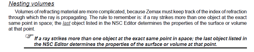
If you make the appropriate changes to your model based on my previous post, you will find that the coupling efficiency goes up as the fiber NA increases (assuming all cladding rays are stripped out in the model). The primary change you need to make is to list the core cylinder *after* the cladding cylinder. It’s very important to understand the nesting rules in non-sequential mode.
Right now your fiber consists solely of a single cylinder having a refractive index of 1.47 (the core cylinder is being completely neglected because of its placement in the component editor spreadsheet). The effective NA of this light pipe is >1.0, meaning any ray that can make it into the cylinder will be guided. When you change the index of this cylinder to 1.36, the effective NA comes down to 0.92, which still significantly exceeds the maximum NA of the incident rays, so your observed coupling efficiency remains pinned at 100%.
Also, your “fiber” is so short that some high-NA input rays can propagate directly to the output surface without ever encountering the cylinder wall. In other words, your fiber isn’t long enough to have it angularly filter and guide rays in the same way that a longer fiber would. Simple geometry shows that doubling the fiber length to 10 mm, combined with properly laying out a 0.22 MMF, will help solve this problem by ensuring that rays with an NA greater than 0.22 have at least one intersection with the core/cladding interface and will therefore not TIR back into the core (and hence are not “guided” in the core). Lastly, I suggest you look carefully at what happens to rays in your cladding. Do you want to strip them out in your model, or allow them to continue propagating? With such a short piece of fiber having a very thin cladding layer you will almost certainly, in practice, have a lot of high-NA cladding rays being guided to the output surface as well.
Your attachment contains only the zda file. It needs also the zmx or zos file. Better yet, save the design as a zar (Zemax archive) and attach that, and you will have saved everything needed for others to open the file.
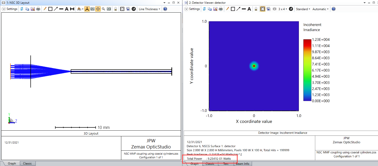
In non-sequential mode, using two coaxial cylinders to represent the core and cladding should work okay for simulation of a multimode fiber (MMF), but there are a few details to take into account. First, in the layout spreadsheet, the cladding cylinder should be listed before the core cylinder. That way the nesting rules associated with object placement will ensure that the core replaces the appropriate portion of the cladding cylinder. Here’s an example using the NA = 0.22 core and cladding refractive indices with a simple 0.20 NA source.
The coupling efficiency is 92.5%. The 7.5% loss is simply Fresnel reflection from the input/output surfaces. This raytrace was done with ray splitting (and hence polarization) turned on, as well as using a linearly polarized source beam. If the fiber NA is increased, the coupling will remain unchanged as expected since all of the non-reflected rays are being guided.
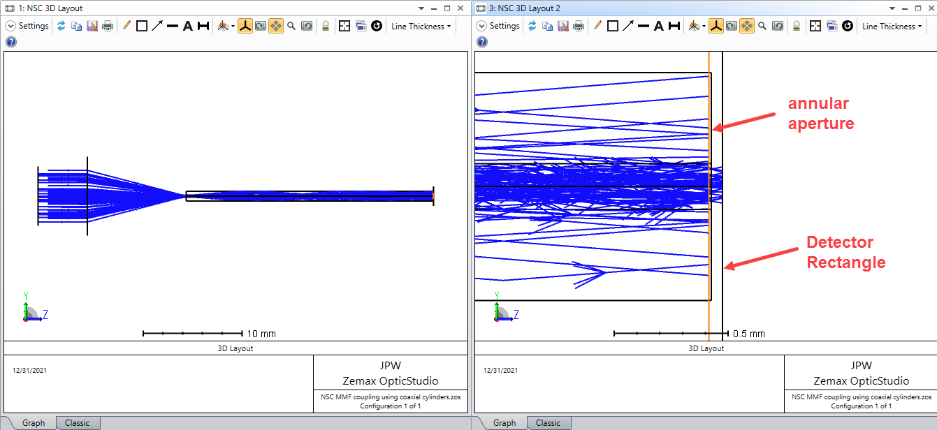
However, if the NA of the source is increased to 0.30, you can see cladding rays show up. So, next, it’s a good idea to use an annular surface at the fiber output as an aperture that blocks cladding mode rays but passes rays that are guiding in the core (i.e., the absorbing annulus has an inner diameter equal to the core diameter).
Also, the outer surface of the cladding cylinder should be made absorbing so that rays don’t TIR off of this surface and make it to the detector. Now the coupling efficiency is reduced to 54.5%. The example file is attached.
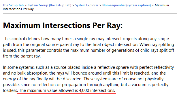
This approach for modeling MMFs is fine, but the fiber length is limited by the maximum number of allowed ray TIR bounces inside the core (which is 4,000).
Based on the maximum NA of the guided rays, this typically corresponds to a fiber length in the range of a few meters.
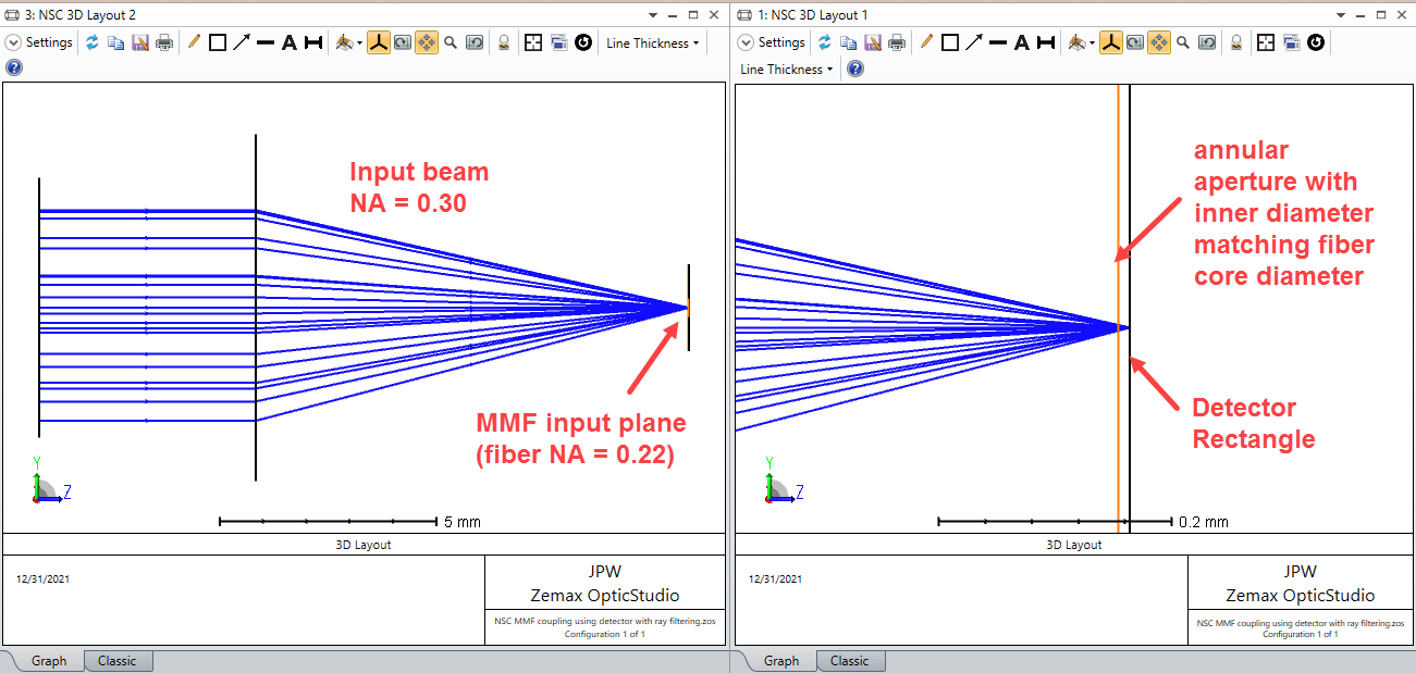
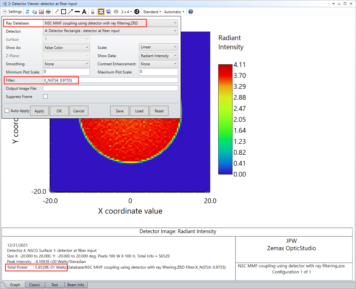
However, there is a simpler and more computationally efficient way to find the coupling efficiency for MMFs. That is to recognize that a MMF is basically a spatial and angular filter for rays, and to use a detector that accounts only for those rays that make it through the filtering process. This can be readily done in sequential mode as described here: How to model multi-mode fiber coupling. A similar approach can be implemented in non-sequential mode using only a detector (no need to physically model the fiber). This is done by placing a detector where the input plane of the fiber resides, inserting an annular aperture immediately in front of the detector (to form the spatial filter), and then using a filter string to look at only those rays that are contained within the acceptance NA of the fiber (i.e., the angular filter). Here’s the layout with a input beam having an NA = 0.30:
To implement the angular filter, we note in the help documentation:
For a fiber NA=0.22, the maximum angle of incidence for guided rays is 12.7 degrees (with cos(12.7) = 0.9755).
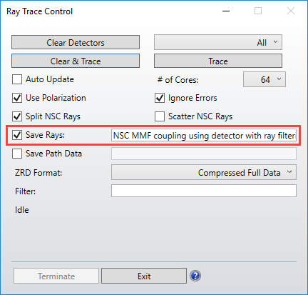
To get the coupling efficiency we run a raytrace and save the ray file.
Then, in the detector viewer, we simply use this ray file and apply the appropriate filter string:
We then see that the coupling efficiency is 56.5%, which is slightly higher than the value we found previously using the coaxial cylinders, but of course this latter approach does not include Fresnel loss so we would expect a somewhat higher value.
Lastly, to model coupling into single-mode fibers, which involves a mode overlap calculation, the best approach is to use the various tools available in sequential mode. (see Single-mode fiber coupling in OpticStudio)
In non-sequential mode, using two coaxial cylinders to represent the core and cladding should work okay for simulation of a multimode fiber (MMF), but there are a few details to take into account. First, in the layout spreadsheet, the cladding cylinder should be listed before the core cylinder. That way the nesting rules associated with object placement will ensure that the core replaces the appropriate portion of the cladding cylinder. Here’s an example using the NA = 0.22 core and cladding refractive indices with a simple 0.20 NA source.
The coupling efficiency is 92.5%. The 7.5% loss is simply Fresnel reflection from the input/output surfaces. This raytrace was done with ray splitting (and hence polarization) turned on, as well as using a linearly polarized source beam. If the fiber NA is increased, the coupling will remain unchanged as expected since all of the non-reflected rays are being guided.
However, if the NA of the source is increased to 0.30, you can see cladding rays show up. So, next, it’s a good idea to use an annular surface at the fiber output as an aperture that blocks cladding mode rays but passes rays that are guiding in the core (i.e., the absorbing annulus has an inner diameter equal to the core diameter).
Also, the outer surface of the cladding cylinder should be made absorbing so that rays don’t TIR off of this surface and make it to the detector. Now the coupling efficiency is reduced to 54.5%. The example file is attached.
This approach for modeling MMFs is fine, but the fiber length is limited by the maximum number of allowed ray TIR bounces inside the core (which is 4,000).
Based on the maximum NA of the guided rays, this typically corresponds to a fiber length in the range of a few meters.
However, there is a simpler and more computationally efficient way to find the coupling efficiency for MMFs. That is to recognize that a MMF is basically a spatial and angular filter for rays, and to use a detector that accounts only for those rays that make it through the filtering process. This can be readily done in sequential mode as described here: How to model multi-mode fiber coupling. A similar approach can be implemented in non-sequential mode using only a detector (no need to physically model the fiber). This is done by placing a detector where the input plane of the fiber resides, inserting an annular aperture immediately in front of the detector (to form the spatial filter), and then using a filter string to look at only those rays that are contained within the acceptance NA of the fiber (i.e., the angular filter). Here’s the layout with a input beam having an NA = 0.30:
To implement the angular filter, we note in the help documentation:
For a fiber NA=0.22, the maximum angle of incidence for guided rays is 12.7 degrees (with cos(12.7) = 0.9755).
To get the coupling efficiency we run a raytrace and save the ray file.
Then, in the detector viewer, we simply use this ray file and apply the appropriate filter string:
We then see that the coupling efficiency is 56.5%, which is slightly higher than the value we found previously using the coaxial cylinders, but of course this latter approach does not include Fresnel loss so we would expect a somewhat higher value.
Lastly, to model coupling into single-mode fibers, which involves a mode overlap calculation, the best approach is to use the various tools available in sequential mode. (see Single-mode fiber coupling in OpticStudio)
Dear Sir,
Thanks for explaning the important things in the above discussion.
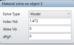
One more doubt I am having How you are changing the NA of fiber, by changing the core and cladding R.I. only?
( Because Fiber NA = sqrt(core_R.I.^2 - cladding_R.I.^2), so NA is depending on the core and cladding R.I. only!)
Like attached screenshot, how I am changing the R.I. in zemax spreadsheet.
Yes, the NA of a step-index MMF is dictated by the core and cladding refractive indices:
In my examples I kept the fiber NA fixed at 0.22, and considered coupling for two different launch beam NA values (0.20 and 0.30).
In your model the light hitting the fiber entrance face is overfilling the fiber both spatially and angularly:
If you make the appropriate changes to your model based on my previous post, you will find that the coupling efficiency goes up as the fiber NA increases (assuming all cladding rays are stripped out in the model). The primary change you need to make is to list the core cylinder *after* the cladding cylinder. It’s very important to understand the nesting rules in non-sequential mode.
Right now your fiber consists solely of a single cylinder having a refractive index of 1.47 (the core cylinder is being completely neglected because of its placement in the component editor spreadsheet). The effective NA of this light pipe is >1.0, meaning any ray that can make it into the cylinder will be guided. When you change the index of this cylinder to 1.36, the effective NA comes down to 0.92, which still significantly exceeds the maximum NA of the incident rays, so your observed coupling efficiency remains pinned at 100%.
Also, your “fiber” is so short that some high-NA input rays can propagate directly to the output surface without ever encountering the cylinder wall. In other words, your fiber isn’t long enough to have it angularly filter and guide rays in the same way that a longer fiber would. Simple geometry shows that doubling the fiber length to 10 mm, combined with properly laying out a 0.22 MMF, will help solve this problem by ensuring that rays with an NA greater than 0.22 have at least one intersection with the core/cladding interface and will therefore not TIR back into the core (and hence are not “guided” in the core). Lastly, I suggest you look carefully at what happens to rays in your cladding. Do you want to strip them out in your model, or allow them to continue propagating? With such a short piece of fiber having a very thin cladding layer you will almost certainly, in practice, have a lot of high-NA cladding rays being guided to the output surface as well.
In non-sequential mode, using two coaxial cylinders to represent the core and cladding should work okay for simulation of a multimode fiber (MMF), but there are a few details to take into account. First, in the layout spreadsheet, the cladding cylinder should be listed before the core cylinder. That way the nesting rules associated with object placement will ensure that the core replaces the appropriate portion of the cladding cylinder. Here’s an example using the NA = 0.22 core and cladding refractive indices with a simple 0.20 NA source.
The coupling efficiency is 92.5%. The 7.5% loss is simply Fresnel reflection from the input/output surfaces. This raytrace was done with ray splitting (and hence polarization) turned on, as well as using a linearly polarized source beam. If the fiber NA is increased, the coupling will remain unchanged as expected since all of the non-reflected rays are being guided.
However, if the NA of the source is increased to 0.30, you can see cladding rays show up. So, next, it’s a good idea to use an annular surface at the fiber output as an aperture that blocks cladding mode rays but passes rays that are guiding in the core (i.e., the absorbing annulus has an inner diameter equal to the core diameter).
Also, the outer surface of the cladding cylinder should be made absorbing so that rays don’t TIR off of this surface and make it to the detector. Now the coupling efficiency is reduced to 54.5%. The example file is attached.
This approach for modeling MMFs is fine, but the fiber length is limited by the maximum number of allowed ray TIR bounces inside the core (which is 4,000).
Based on the maximum NA of the guided rays, this typically corresponds to a fiber length in the range of a few meters.
However, there is a simpler and more computationally efficient way to find the coupling efficiency for MMFs. That is to recognize that a MMF is basically a spatial and angular filter for rays, and to use a detector that accounts only for those rays that make it through the filtering process. This can be readily done in sequential mode as described here: How to model multi-mode fiber coupling. A similar approach can be implemented in non-sequential mode using only a detector (no need to physically model the fiber). This is done by placing a detector where the input plane of the fiber resides, inserting an annular aperture immediately in front of the detector (to form the spatial filter), and then using a filter string to look at only those rays that are contained within the acceptance NA of the fiber (i.e., the angular filter). Here’s the layout with a input beam having an NA = 0.30:
To implement the angular filter, we note in the help documentation:
For a fiber NA=0.22, the maximum angle of incidence for guided rays is 12.7 degrees (with cos(12.7) = 0.9755).
To get the coupling efficiency we run a raytrace and save the ray file.
Then, in the detector viewer, we simply use this ray file and apply the appropriate filter string:
We then see that the coupling efficiency is 56.5%, which is slightly higher than the value we found previously using the coaxial cylinders, but of course this latter approach does not include Fresnel loss so we would expect a somewhat higher value.
Lastly, to model coupling into single-mode fibers, which involves a mode overlap calculation, the best approach is to use the various tools available in sequential mode. (see Single-mode fiber coupling in OpticStudio)
Hi Jeff,
I just have designed the same optical system which has source - fiber structure to investigate fiber coupling. ( CORE diameter 100 um, CLADDING diameter 200 um )
Furthermore, I got trouble with setting NA of source and making focal spot at the front of fiber in NSC mode. So I have tried to download your attachment to understand the overall structure, but It couldn’t be opened.
I think this is because It passes 2 years and file has been broken.. the other attachments are easily downloaded.
If you don’t mind I wish you upload this attachment once again. I want to investigate designing NA of source and fiber coupling in NSC mode.
I also appreciate the author as I could understand NA of fiber through this question ! It really helps me well
We use 3 different kinds of cookies. You can choose which cookies you want to accept. We need basic cookies to make this site work, therefore these are the minimum you can select. Learn more about our cookies.