This is my first time posting so I will do my best to communicate this effectively. I have an assembly exported from Solidworks as a STEP file (exploded) and I am looking to rotate an object on its own axis within the assembly. When I attempt to utilize the Tilt parameters the object makes a large translation in space as well as rotates, as if orbiting a center point a considerable distance away (perhaps the origin of the assembly). I have looked to un-reference the part to the assembly and attempt to rotate it, but it still continues to translate it considerable distances seemingly unaffected.
This does not seem to be a unique problem to myself, and I have seen solutions suggested to similar issues on here that one needs to introduce a dummy object to reference the desired part to. However since the assembly does not note the coordinates of each of its parts (all parts are listed as (0,0,0) as seems to be the standard), determining how to place the dummy object has been rather difficult. I am having to guess where the correct alignment would be as opposed to placing it directly on axis with it. I have been looking in the manual under reference objects and non-sequential but have found little clarity here.
Am I missing an obvious way to find object placement information? Or am I overlooking a simple way to rotate the object? Any insight would be greatly helpful as these are my first experiences in non-sequential mode.
Thank you
Best answer by David.Nguyen
Hi ACaputo,
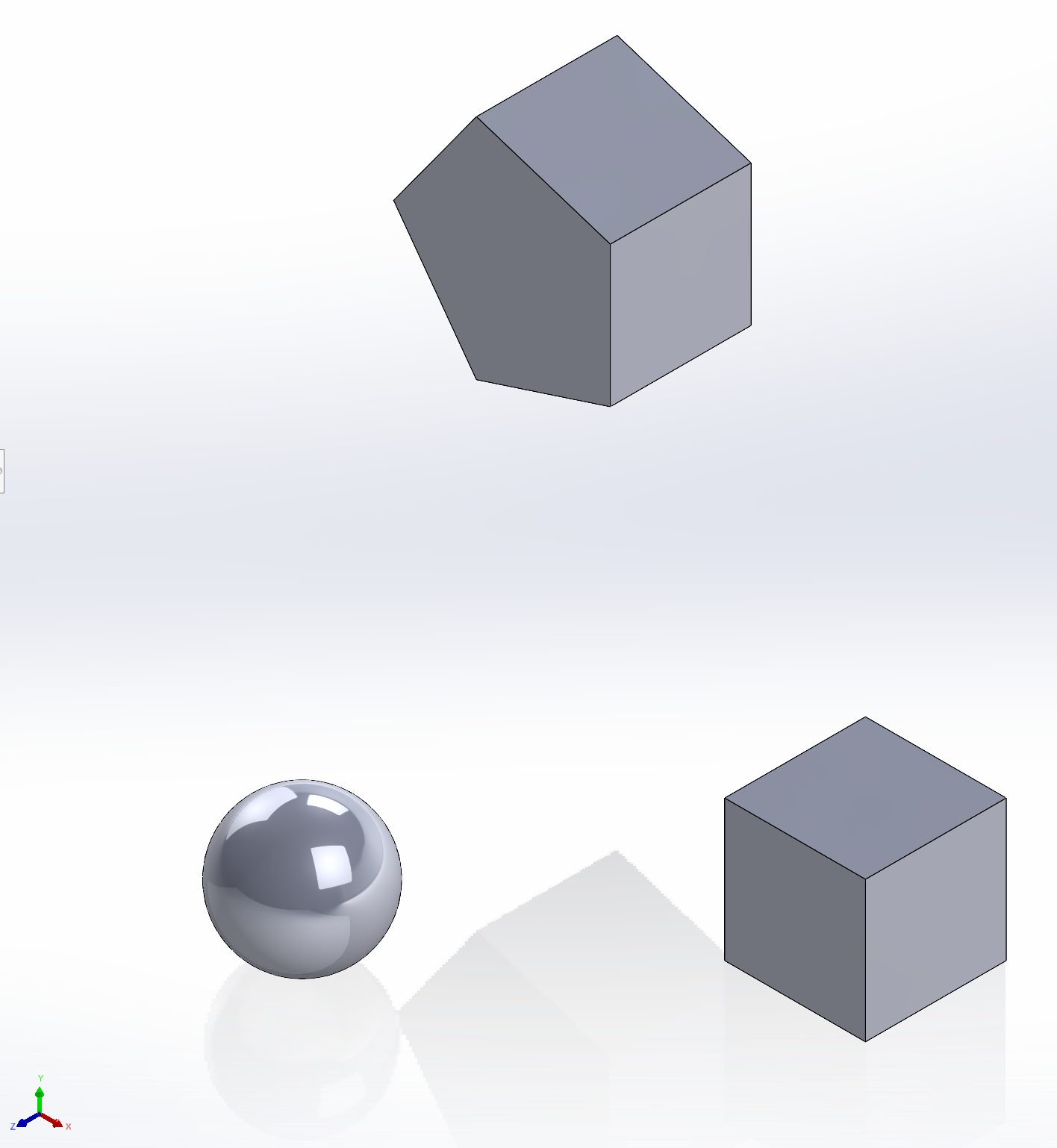
To illustrate how I’d go about this problem, I made a Solidworks (SW) assembly of three geometrical shapes, this is what it looks like on an isometric view:
Isometric view in Solidworks of an assembly of three shapes: a sphere, a cube, and a pentagonal prism. The origin is at the barycentre of the sphere.
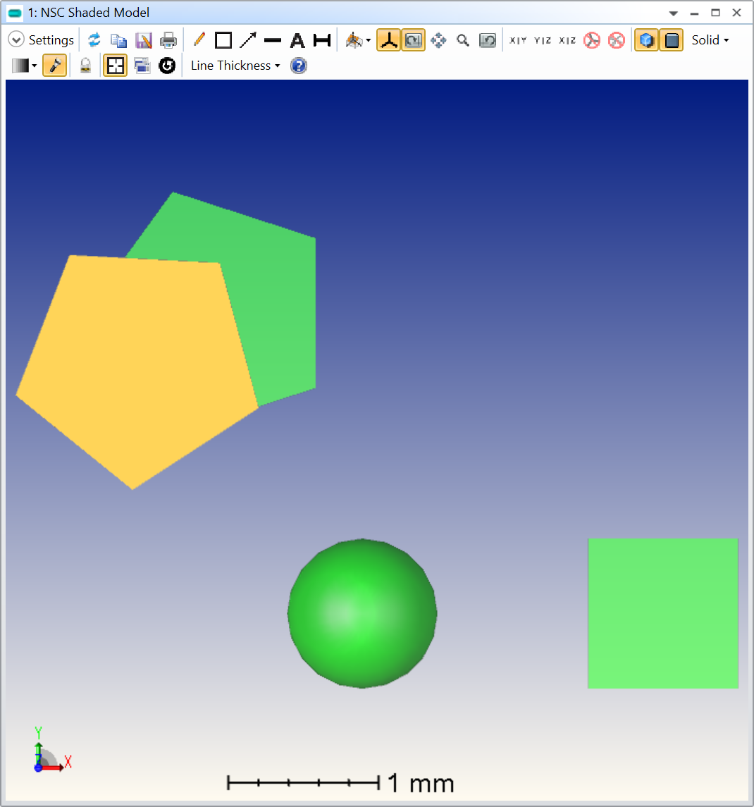
I then exported the assembly as a single *.STEP file and opened it in OpticStudio (OS):
Same assembly imported in OpticStudio as a *.STEP file. One can observe that the coordinate system is rotated about Y by 180 degrees.
The first (anecdotal) thing to notice is that the coordinage system is rotated about the Y axis by 180 degrees when using the isometric view. When importing a *.STEP file in OS, the origin in the STEP file is preserved. Meaning that in this particular case, it is still the barycentre of the sphere. We can confirm this by rotating the whole assembly using the Tilt About X/Y/Z columns in an X-Y projection for example:
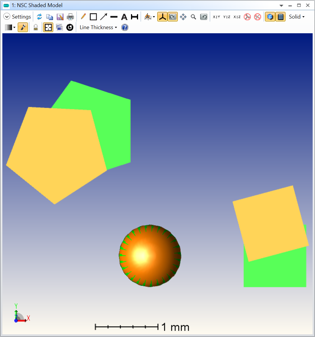
The assembly was imported twice without changing its default location. A Tilt About Z of 15 degree was apply to one of the assembly. As expected, the rotation happens around the sphere, where the origin is.
I let you check that all the rotations are made about the sphere in the other projections (Y-Z and X-Z).
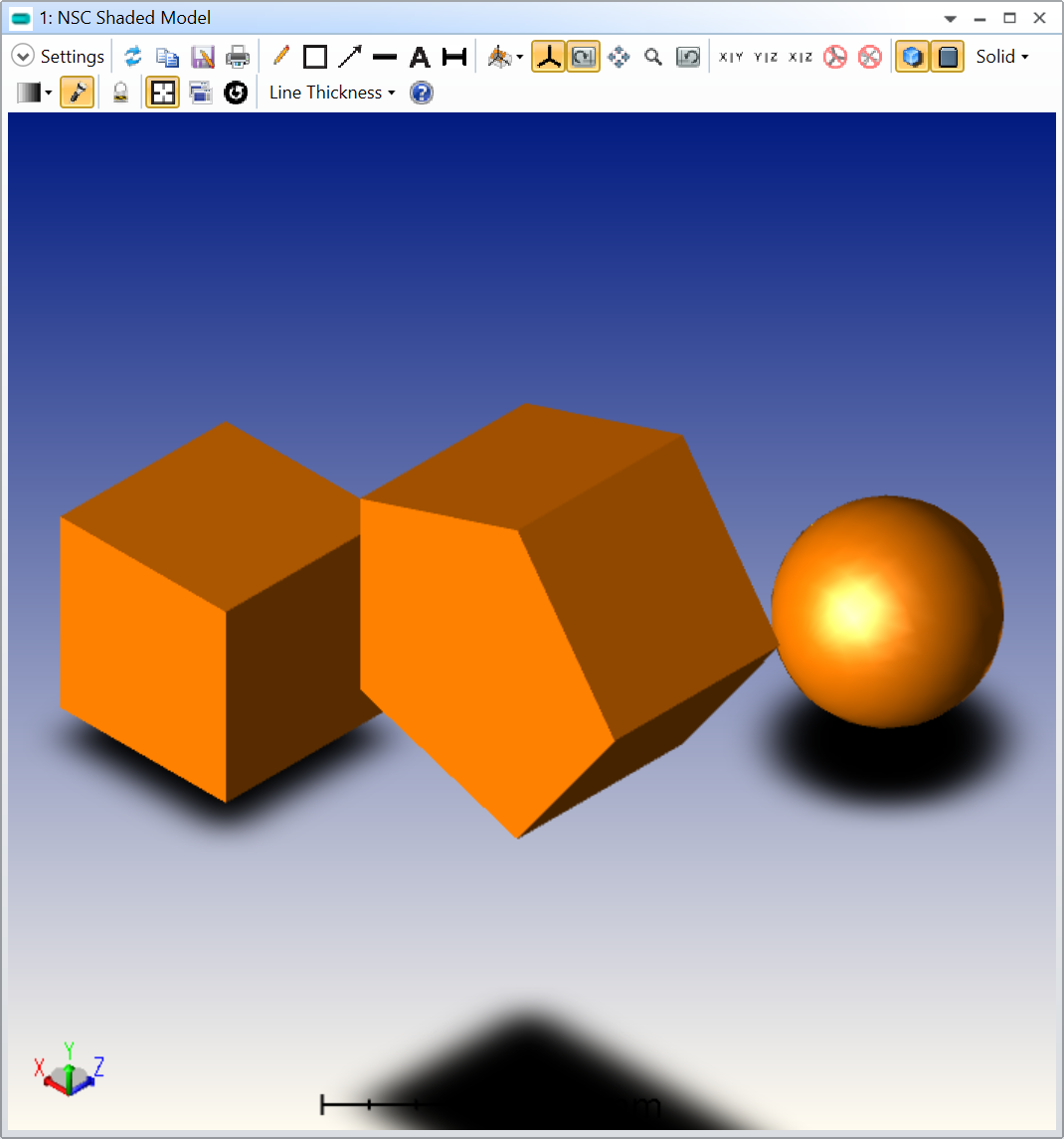
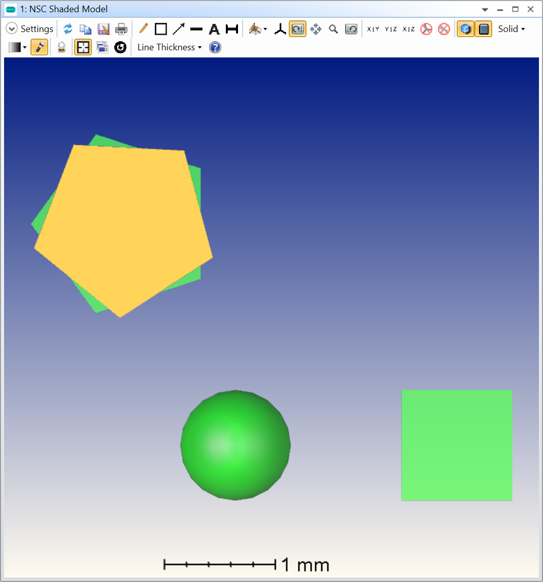
If you explode the assembly, and rotate only the pentagonal prism by 15 degree, this is what you would see in an X-Y projection (I kept the whole assembly in green and increased its transparency):
Exploded pentagonal prism (in orange) is rotated by 15 degrees about Z in a X-Y projection. The shaded model also contains the original assembly (in green). The rotation is still done about the origin of the whole assembly, meaning the sphere.
As you can see, the rotation is still done about the origin of the whole CAD assembly, or the sphere in this particular case. Let’s now see how you can rotate the pentagonal prism about its barycentre.
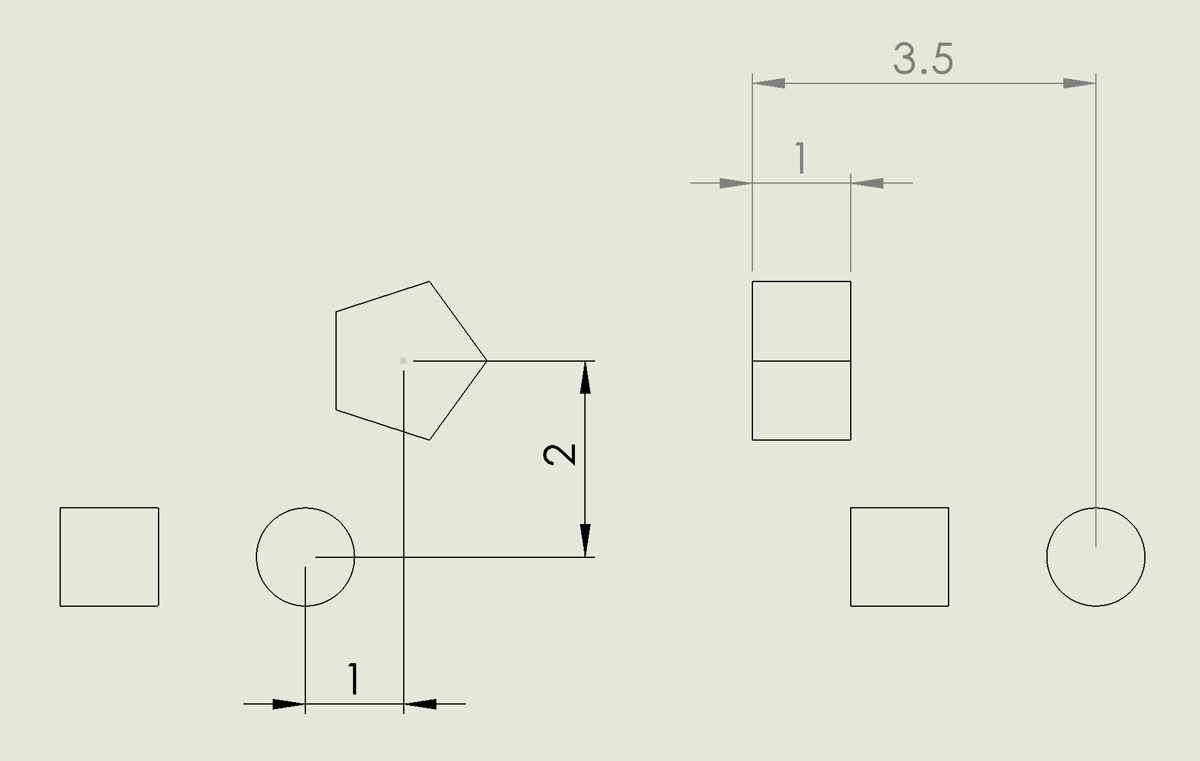
First, let’s look at a (poor) drawing of the assembly:
Drawing exposing the location of the pentagonal prism with respect to the origin.
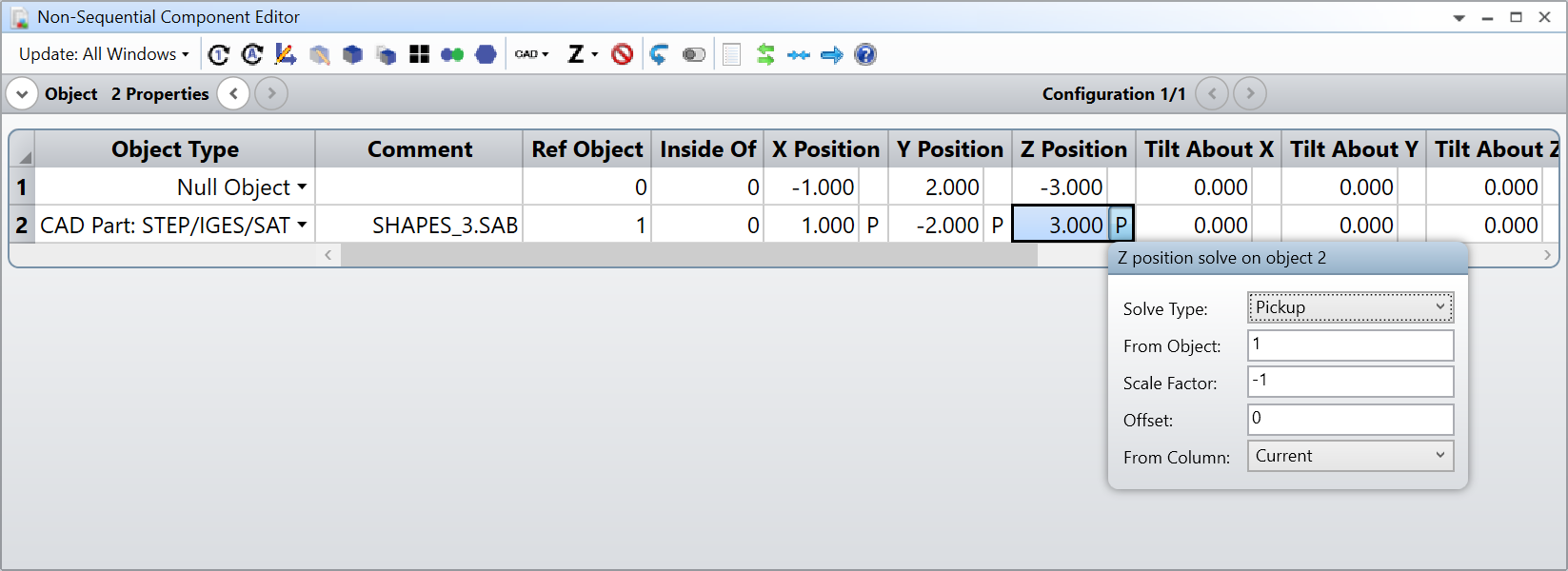
This shows the actual location of the pentagonal prism with respect to the assembly origin (the sphere). This is were it gets a little bit tricky, but bear with me. The idea is to insert a Null Object before the exploded pentagonal prism, and change the location of this dummy object (X/Y/Z Position) to the location of the pentagonal prism. In SW, the pentagonal prism is located in X = -1.0, Y = 2.0, and Z = -3.0 so we’ll use those exact same values in OS. Then, I’ll use the Ref Object colunn of the pentagonal prism and type in the Null Object number. That way, the pentagonal prism location is referenced to the Null Object. However, this moves the pentagonal prism from its original location. We bring it back by settings Pick-up solves with a -1.0 factor from the Null Object.
In the layout, everything will seem as if the pentagonal prism hasn’t changed. But we now have access to the location of the barycentre of the pentagonal prism through the Null Object. If you try rotating the Null Object about Z by 15 degrees this is what you’ll see:
Rotation of 15 degrees about Z of a Null Object located at the pentagonal prism barycentre location.
I leave you to check the other rotations, and you can try to do the same for the cube. I’m attaching all these files to my answer.
To illustrate how I’d go about this problem, I made a Solidworks (SW) assembly of three geometrical shapes, this is what it looks like on an isometric view:
Isometric view in Solidworks of an assembly of three shapes: a sphere, a cube, and a pentagonal prism. The origin is at the barycentre of the sphere.
I then exported the assembly as a single *.STEP file and opened it in OpticStudio (OS):
Same assembly imported in OpticStudio as a *.STEP file. One can observe that the coordinate system is rotated about Y by 180 degrees.
The first (anecdotal) thing to notice is that the coordinage system is rotated about the Y axis by 180 degrees when using the isometric view. When importing a *.STEP file in OS, the origin in the STEP file is preserved. Meaning that in this particular case, it is still the barycentre of the sphere. We can confirm this by rotating the whole assembly using the Tilt About X/Y/Z columns in an X-Y projection for example:
The assembly was imported twice without changing its default location. A Tilt About Z of 15 degree was apply to one of the assembly. As expected, the rotation happens around the sphere, where the origin is.
I let you check that all the rotations are made about the sphere in the other projections (Y-Z and X-Z).
If you explode the assembly, and rotate only the pentagonal prism by 15 degree, this is what you would see in an X-Y projection (I kept the whole assembly in green and increased its transparency):
Exploded pentagonal prism (in orange) is rotated by 15 degrees about Z in a X-Y projection. The shaded model also contains the original assembly (in green). The rotation is still done about the origin of the whole assembly, meaning the sphere.
As you can see, the rotation is still done about the origin of the whole CAD assembly, or the sphere in this particular case. Let’s now see how you can rotate the pentagonal prism about its barycentre.
First, let’s look at a (poor) drawing of the assembly:
Drawing exposing the location of the pentagonal prism with respect to the origin.
This shows the actual location of the pentagonal prism with respect to the assembly origin (the sphere). This is were it gets a little bit tricky, but bear with me. The idea is to insert a Null Object before the exploded pentagonal prism, and change the location of this dummy object (X/Y/Z Position) to the location of the pentagonal prism. In SW, the pentagonal prism is located in X = -1.0, Y = 2.0, and Z = -3.0 so we’ll use those exact same values in OS. Then, I’ll use the Ref Object colunn of the pentagonal prism and type in the Null Object number. That way, the pentagonal prism location is referenced to the Null Object. However, this moves the pentagonal prism from its original location. We bring it back by settings Pick-up solves with a -1.0 factor from the Null Object.
In the layout, everything will seem as if the pentagonal prism hasn’t changed. But we now have access to the location of the barycentre of the pentagonal prism through the Null Object. If you try rotating the Null Object about Z by 15 degrees this is what you’ll see:
Rotation of 15 degrees about Z of a Null Object located at the pentagonal prism barycentre location.
I leave you to check the other rotations, and you can try to do the same for the cube. I’m attaching all these files to my answer.
I hope this helps. Take care,
David
Hi David,
Wow this is very thorough! Thank you so much for taking the time, I think this cleared up a lot. Playing with this file helped to put together what you were describing as well.
The big connection for me was the need to set the coordinates of the null object to be exactly at the coordinates of the desired object. I have this Zemax file provided by someone else, without my own access to the original solidworks file. So what this is telling me is there is no way to rotate this object about itself without knowing its real coordinates in the assembly, correct?
I just find it strange (perhaps due to being new to Non-Sequential Systems), that although the assemblies retain the positional data of each part by way of their placement, that it cannot be accessed or verified within Zemax. You actually need to go reference the Solidworks model for the numerical coordinates, is that correct?
To the best of my knowledge, you are quite correct with your first question. There are ways to locate non-sequential objects by using known rays and figuring out how they intersect with the object, but this is far less convenient than in a more traditional CAD software.
One thing I don’t know though is that every part has an origin as well. And I think you are correct that somehow in the *.STEP this information must be conveyed. But, if you don’t know where that origin is for the individual elements (it might not be where you think it is), because this file was just passed on to you, the problem might be even worse.
It would be worth asking the CAD people at Zemax, someone like @Flurin Herren perhaps?
But as far as I know, you’d indeed have to get the positions of your individual components in Solidworks to then input in OpticStudio.
Thanks for posting in the forum. As David has already covered the introduction and basics in great detail, let me pick up on the second question.
Q: So what this is telling me is there is no way to rotate this object about itself without knowing its real coordinates in the assembly, correct?
Yes, there is no straight forward way of retrieving the local coordinates of a specific part of an exploded system within OpticStudio. The main reason for that is here is that the meshed CAD Parts have to be fitted into the modeling approach of OpticStudio, which in NSQ can be described as a hybrid between a “first-guess-meshed” and then equation driven surface. For more information allow me to reference to the follow articles:
So, I can see two workaround approaches (WA) here:
WA1: David has already briefly mention that you could use rays and ray filter in order to see where objects and rays intersect and get the coordinates this way. But this is connected with quite a bit of effort.
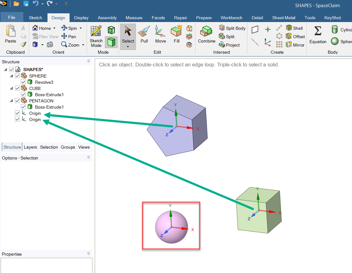
WA2: I am not sure how complex your system is, but you won't need to go back to the actual design if you have the STEP assembly. Because other than OpticStudio can other CAD Platforms display the local coordinates of a part within an assembly quite easily. As an example, I took the STEP Assembly which David has created in SW and opened it up in Ansys SpaceClaim:
In red you can see the Global Coordinate Origin, which is in the middle of the sphere. And in green, you can see the two created local coordinate points for the other two objects.
Having said all of that, I agree with both of you that this information must be conveyed in some shape or form, otherwise OpticStudio would not be able to explode the CAD Assembly properly.
Let me run that past the Product Team quickly and see if they can help us a bit further here. We could potentially also file a feature request if necessary, to make this workflow a bit easier in the future.
Feel free to ask any follow-up question you might have,
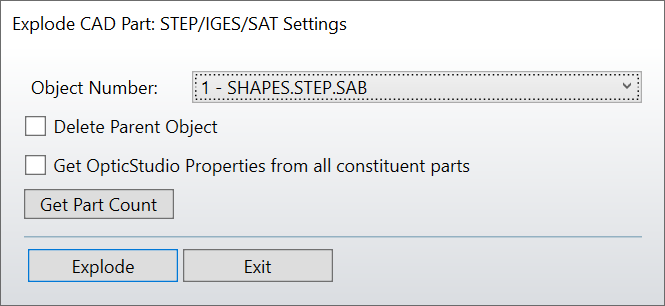
Thanks for the answer @Flurin Herren. One thing I noted is that if you try to explode the part from the Non-Sequential Component Editor, there’s a checkbox called Get OpticStudio Properties from all constituent parts.
I tried exploding the assembly with and without this checkbox and it didn’t seem to make a difference. Do you know what this is for? For a second I thought it could be what we were looking for.
This Check box reads in any optical properties that have previously been saved to the individual parts using the Save CAD Assembly/Part Properties tool. The CAD Assembly/Part Properties saves optical properties of an (dynamic!)-object back in that programs format.
So, this would only be useful with optical properties of the parts and subsequentially only be used with Creo or Inventor Parts (Parametric CAD Parts, Dynamic Link). Thus, I don't really see the point of having this within the STEP Explode dialog window. I`ll pass that on.
Great to see some more discussion about this topic and that this might be better conveyed in the future. This led me to an additional tangential question to ask, does the same issue apply for referencing non assembly objects (sources, detectors, new objects) to the assembly. I have attempted to reference a source to a particular part # to help center its location but also find that it seemingly does nothing, and keeps the source bound within the assembly coordinate system. Is this a similar issue with the rotation, or is this a separate difficulty?