I followed the Zemax tutorial for how to optimize a simple lens in OpticStudio.
What I would like to do is create a lens for collimating a beam but which is optimized to reduce higher order aberrations. I don’t want to worry about spherical aberration, because we can reposition the fiber to different distances at different angles.
I’m not sure how to configure such a thing given the optimization wizard shown in the tutorial. Is there an easy way to specify this is what I want to do so the optimizer knows that?

Solved
Removing spherical aberration from optimization
Best answer by Jeff.Wilde
I can add a few comments in addition to what David has said. First, I think you may be confusing spherical aberration with defocus. They are two different aberrations, and often some amount of defocus can be helpful in balancing spherical aberration. Second, if you are designing the lens in reverse (in other words, collimated beams in object space are being optimally focused at the image plane, which is the standard imaging-at-infinity configuration) then I think you are asking if there is a way to ignore field curvature in the merit function. I think the answer is yes, if you set up the model so that each field angle corresponds to a separate configuration, and allow each configuration to have its own variable image plane distance. That way each field angle (i.e., each incoming collimated beam) can be optimally focused, which is a way of taking field curvature out of the problem.
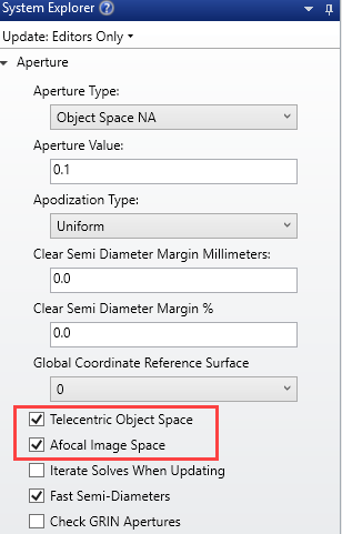
However, with all that being said, I think you may actually be better off designing the lens using point-source fields, and then optimize for best collimation in image space. I say this because I assume you are using a single-mode fiber as the source, and it sounds like you can adjust its position in three dimensions (x,y,z). However, I’m also going to assume that you will not actively tip/tilt the fiber, but rather keep its axis parallel to the z-direction. If that is indeed the case, then you can set up your model to be telecentric in object space and afocal in image space:
Here’s an example two-field layout using the sample even asphere lens (flipped around to collimate the point sources):
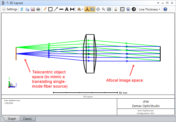
As I mentioned previously, you can use the multi-configuration feature to put a single field point in each configuration (the fields should now be based on *position* in the object plane, not angle). Each configuration can then have its own object-to-lens distance, set as a variable (along with whatever lens parameters you want to optimize). Here’s the two-field (i.e., two configurations) example with only the focal position being varied:
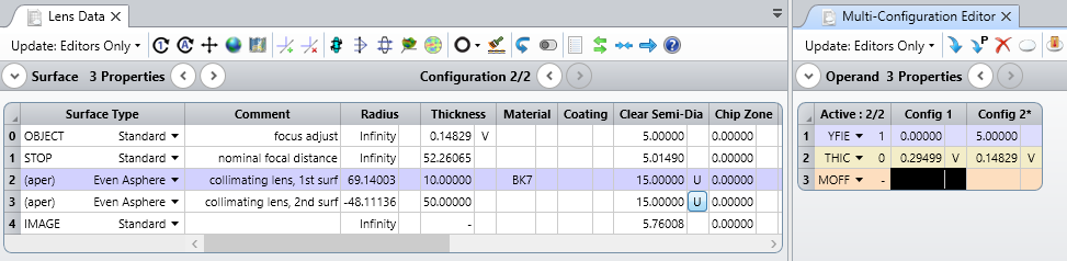
Lastly, use the merit function wizard with RMS wavefront as the “image quality” target. Now when you optimize, each field point (at a specific x,y location) can have its z-position vary as well, which mimics your ability to move the fiber along the z-direction. As you can see above, after optimization, the two fields have slightly different shifts along the z-axis, separated by about 150 um.
Does this make sense? Hope it helps...


Enter your E-mail address. We'll send you an e-mail with instructions to reset your password.
Need more help?
To Chinese users:
Do not provide any information or data that is restricted by applicable law, including by the People’s Republic of China’s Cybersecurity and Data Security Laws ( e.g., Important Data, National Core Data, etc.).
不要提供任何受适用法律,包括中华人民共和国的网络安全和数据安全法限制的信息或数据(如重要数据、国家核心数据等)。