Hello Everyone,
Does anybody have an idea about how to read out the coordinate values of 3D object corners? In either merit function or ZPL environment is welcomed.


Hello Everyone,
Does anybody have an idea about how to read out the coordinate values of 3D object corners? In either merit function or ZPL environment is welcomed.
Best answer by MichaelH
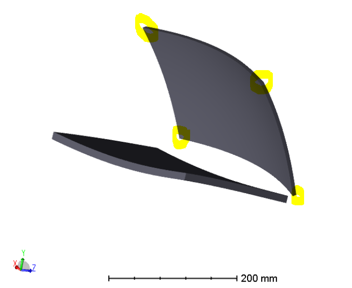
Hi Onder,
Unless there is very simple geometry like a tilted (use Global Rotation Matrix) rectangle (use Half Width X/Y), then you’ll probably have to use ray tracing to determine the extent of the surface or object you’re trying to investigate. OpticStudio itself doesn’t really even keep track of values like the extent of a geometry part and when it does calculate the extent on the fly, it uses ray tracing.
Whether you are in sequential or non-sequential mode, you have 2 options: use the Sag Map to determine the edge/corner of the part (and rotate to global coordinates if needed) or manually calculate the edge of the part in ZPL or MFE.
Sequential Mode
The Sag Map is located under Analyze > Surface > Sag and the following KBA goes into detail about the rotation matrix.
Rotation Matrix and Tilt About X/Y/Z in OpticStudio – Knowledgebase (zemax.com)
For manual calculations:
RAYTRACEX with the starting surface being the surface under investigationRAYV(n) on the surface under investigation to see if the result is 0: RAYV(n) is 0, then the ray hit the part and you haven’t found the corner yetRAYV(n) is 0, then ray is vignetted (outside the aperture of the part)Non-Sequential Mode
The Sag Map is located under Analyze > NSC Sag.
For manual calculations:
Enter your E-mail address. We'll send you an e-mail with instructions to reset your password.
Do not provide any information or data that is restricted by applicable law, including by the People’s Republic of China’s Cybersecurity and Data Security Laws ( e.g., Important Data, National Core Data, etc.).
不要提供任何受适用法律,包括中华人民共和国的网络安全和数据安全法限制的信息或数据(如重要数据、国家核心数据等)。
