Question

Raytracing a Step file

  • 31 July 2023
  • 3 replies
  • 157 views

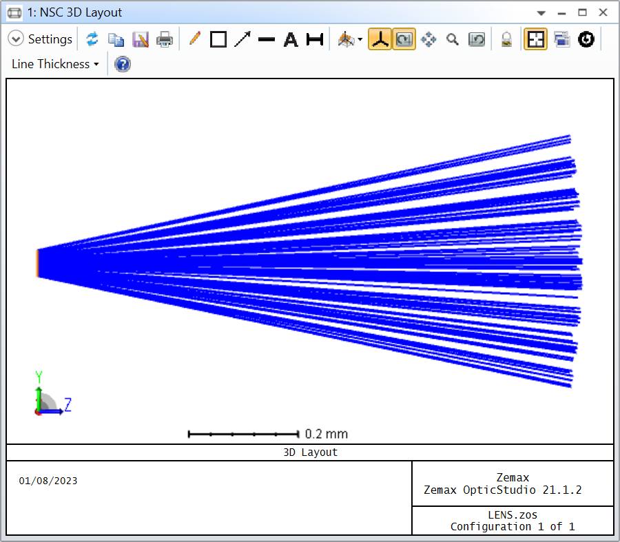
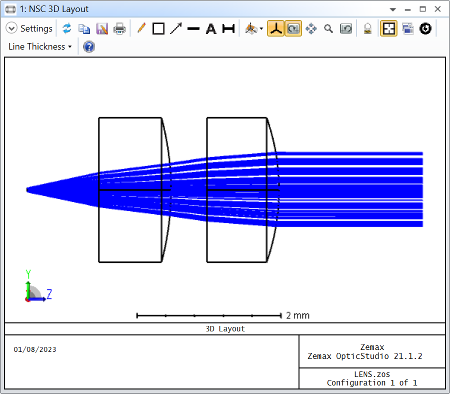
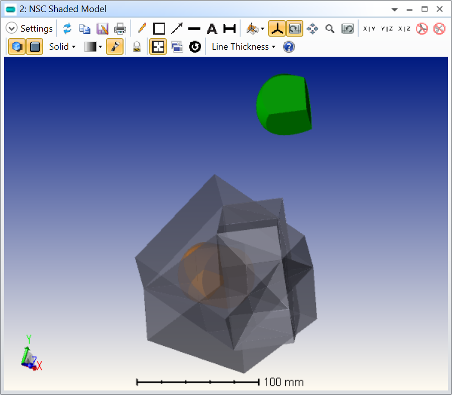
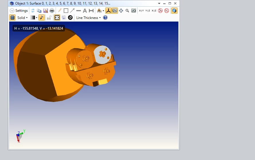
I have imported a collimator that I made in Solidworks  into Zemax and started a non-sequential raytrace, I would like to send rays throughs my four lenses but can’t to figure out how to do so. 


3 replies

Userlevel 7
Badge +2

Hi @Austin.ski22,


This post is a duplicate of:

In general, its a good practice to avoid posting the same question multiple time as you risk having people give an answer to a topic that was already answered elsewhere.

One reason you didn’t get an answer could be because you didn’t give a lot of detail to a quite specific question. I think what would help is:

  1. How did you make the collimator in Solidworks? Typically, you to the optical design in parallel with the mechanical one to assess the performance of the optical system.
  2. In your original design, do you know where the light source should be with respect to the Solidworks assembly origin? Have a look at this post as well.
  3. What are you trying to achieve exactly? If you want to assess the performance of the collimator, you might make things more complicated  than they should be by including the full step file.
  4. If this is an assembly, you will have to explode it to assign different materials to your lenses and coating (or assign different reflectivities) to your mechanical elements.
  5. Can you share what you’ve done already with us?

Hopefully addressing some of the above will attract more attention from the community and you’ll finally get an answer to your question.

Take care,


David


Hi David,

Thanks for the feedback. Essentially What I am trying to accomplish is if I sign laser light out of a GIF 50 fiber individually where are the rays going to hit on the object that is set up across the collimator in the photo of the assembly I uploaded. The object in question here is the 49-015 corner cube from Edmund Optics which is fused silica. I hear what you are saying of that I have to change the material and explode the assembly. Is there a beet way to go about it? My lens are H-LAK10 & H-ZF52 and I just want to shine laser light through the lens assembly to see where the light will hit the corner cube to see if we can reflect the light back.

Userlevel 7
Badge +2

Hi @Austin.ski22,


My general engineering recommendation is always to have a clear goal in mind. Then, design the simplest possible system that can help you achieve that goal. And only make the system more complex if the goal cannot be reached.

Then, I would always suggest thinking carefully about whether the simplest possible system can be made in sequential mode. The sequential mode has the advantage that it is quite efficient in terms of raytracing thanks to the Gaussian quadrature (generally only a handful of rays are traced to compute the various analyses and operands).

If you have to resort to non-squential, my recommendation would be to stay away from CAD files as much as possible. The short reason is that ray tracing through CAD file is slow. You can read more about it here:

https://support.zemax.com/hc/en-us/articles/1500005487401-Improving-non-sequential-ray-tracing-speeds-with-nested-and-Boolean-objects

In essence, you want a simple model where raytracing is fast so that you can rapidly assess the overall suitability of your model. If you start with a complex CAD and you need to trace a lot of rays its going to take so long to get a result and if you need to make modifications it’ll be even longer.

I feel like your problem could be implemented in sequential mode, but I also see some advantages of doing it in non-sequential for the future (things like straight light analysis). So, assuming you decide to carry on with non-sequential. Here would be my recommendations.

For the light source, I don’t know what a GIF 50 fiber is (and didn’t find anything relevant in Google either), but you could start by approximating it with a Source Ellipse object. This is particularly relevant in the case of a multimode fiber. As an example, say you have a multimode fiber with a 50-um core diameter, and a NA of 0.22. In the Source Ellipse, you can set the X Half Width, Y Half Width to 0.025 mm (this is almost self-explanatory), and the Source Distance to 0.111 mm. The Source Distance you can calculate based on the NA, a NA of 0.22 means an emission half-cone angle of arcsin(NA) in air or 12.71 degree. If you want marginal rays to exit the fiber end at this angle its as if a point source was emitting from within the fiber and this is the Source Distance. Since you know the fiber core radius (0.025 mm), the Source Distance is 0.025 / tan(12.71) = 0.111 mm.

Next, you have two lenses for your collimator. I’m assuming you know the shape of those lenses, and for them you can use the Standard Lens object. I made a rudimentory collimator using the materials you suggested and Standard Lens objects.

Lastly, for the corner cube, I’ve made extensive use of the nesting rule as documented in the link I sent previously. Basically, I’ve used a Cylinder volume object that I sliced with Rectangular Volumes. The result looks like so.

In orange is the Cylinder Volume made of fused silica, and it is intersected by three rectangular volumes. The front face of each Rectangular Volume is made reflective. Carefully notice how I’ve setup the editor including the Ref Object column (everything refers to the Null Object 1 so if I move Object 1, everything moves together).

If you have some doubts about the actual construction of the corner cube, you can always double check with a Boolean Native object (but I would not actually use a Boolean Native because it traces slower than simply using the nesting rule). Here’s what it would look like when I offset the Boolean Native (in green) for visibility.

The way this works with the nesting rule is that whenever two objects overlap, the one that has a greater row number will be considered in the overlapping region. So, when a ray enters the Cylinder Volume it travels up until it reaches the front face (reflective) of a Rectangular Volume and is then reflected.

Now, if you put everything together you get the following (I’ve used the Boolean Native object for display, but I’d not use it for ray tracing). I’ve also fletched the rays so you see their direction of travel.

My mistake is that my collimator lenses are ridiculously small whereas the corner cube is to scale, but hopefully you get my point. I’m attaching this file to my answer as well. I live it to you as an exercise to put your output collimator.

There’s a lot to unpack in this reply, take the time to study it carefully. And please let me know if something is unclear (I might be away for some time, but I’ll keep an eye out).

Take care,


David

Reply