Radially Non-symmetric (Linearly Cut) Grid Sag Data of Mirror Surface (Sequential)

  • 22 December 2020
  • 5 replies
  • 120 views

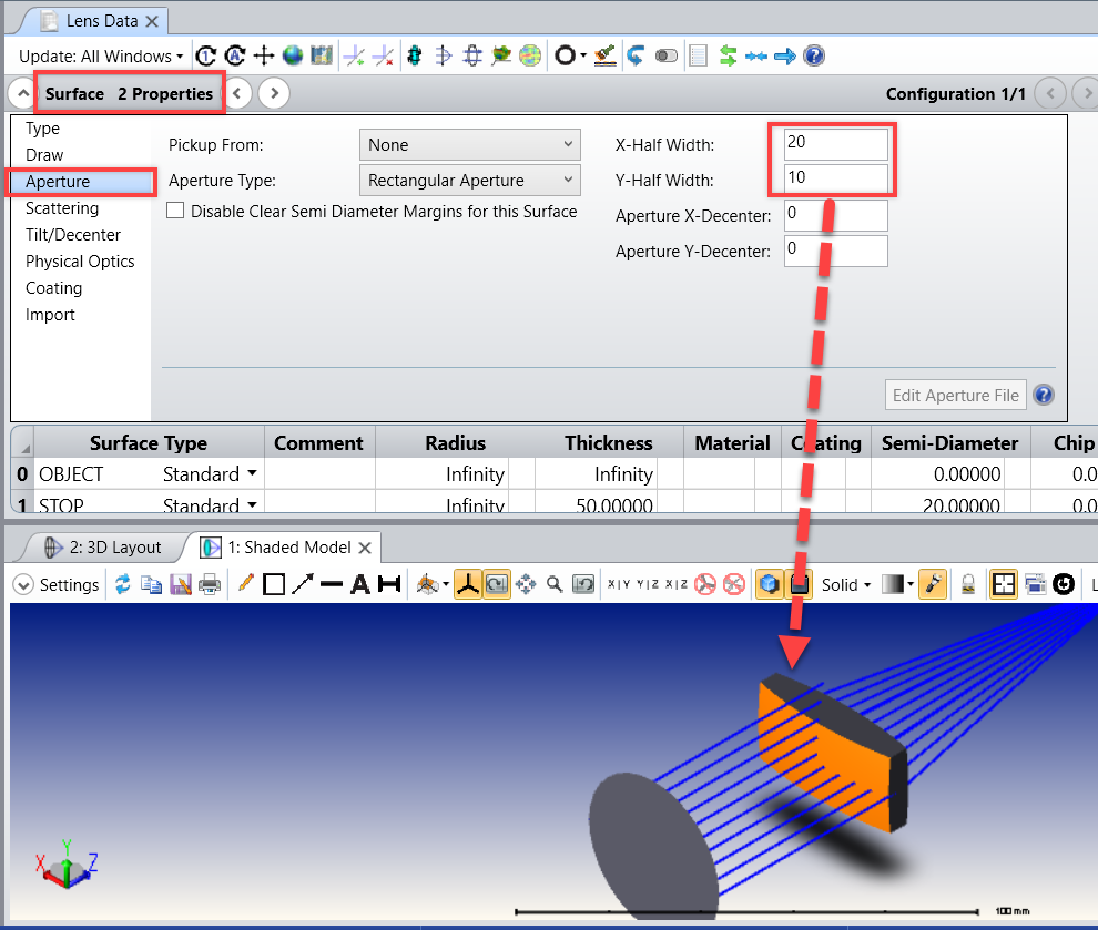
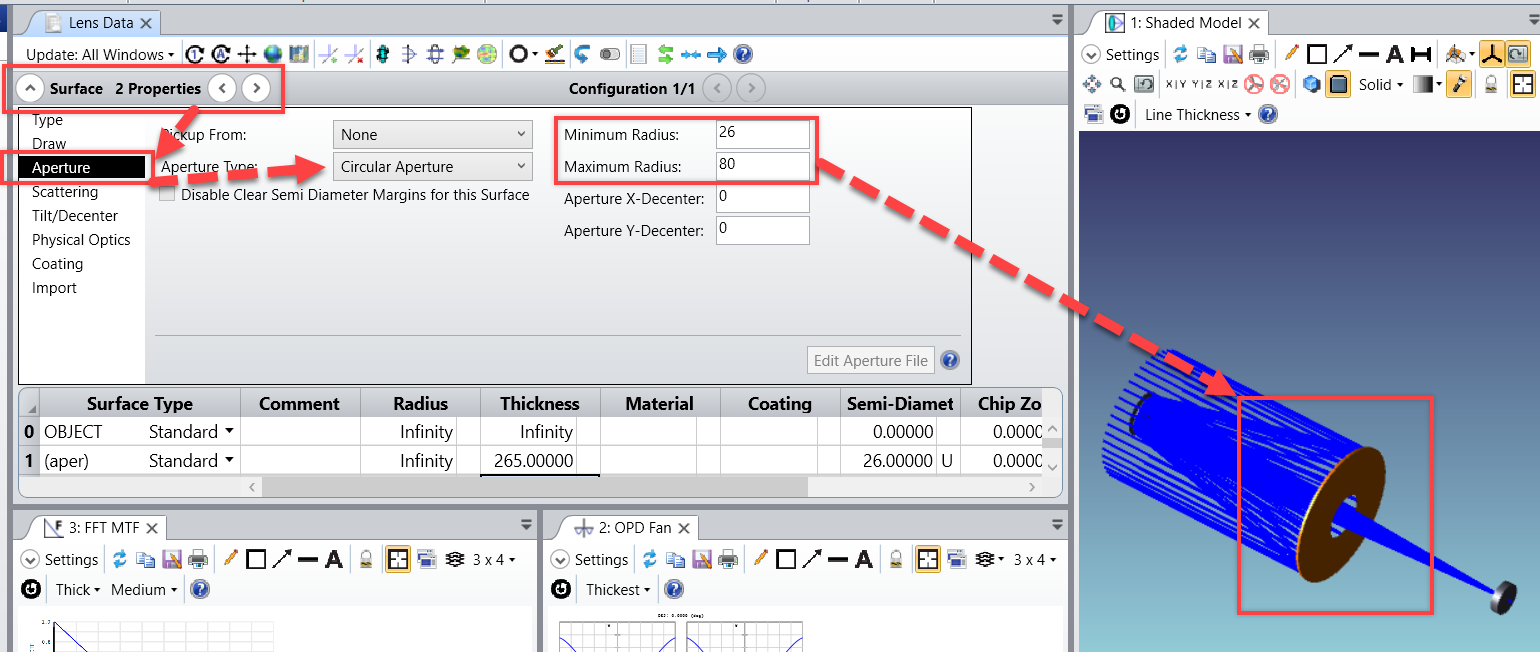
We would like to import a surface sag dat file of a mirror (even asphere plus surface form) surface into our zemax layout for sequential simulation. Our mirror is circular but it is cut in one edge, y > |L| = 0 (Air). We have this easy equation in x,y of the cut mirror. Our question is, since it is not radially symmetric, what is the platform to describe the suface analytically with equation? Should we write the equation into .dat file? Can you please help on the steps to generate this Grid surface sag, if this is possible to be done?


Thank you


5 replies

Userlevel 6
Badge +2

Hi Can,


Based on what you've outlined here, it sounds like you have a mirror that can be described by a single sag equation, but is 'chopped.' In other words, it has an aperture applied that makes it non-circular. Is that correct?


In that case, I would recommend writing the DAT file, importing it, then applying a surface aperture. Here is what I mean:


1. Use the Knowledgebase article 'How to write a Grid Sag DAT file programmatically' to write a DAT file based on the equation you have. Make the DAT file nxn where 'n' is equal to the maximum length of the mirror. 


2. Open OpticStudio and import the DAT file by following the instructions in this Knowledgebase article


3. Now, cut your mirror into the expected shape by applying a surface aperture. You can apply an elliptical, rectangular, or unique aperture to your mirror. Here is an example:


Would that work for you? Alternatively, if you already have a DAT file with appropriate format, you can skip step 1. 


Let us know if you have any other questions about this!


Best,


Allie

Hi Allie,


As you say it is a circular mirror chopped with Y width but, we do not have an equation, just the measured sag datas.We have a DAT file of sag values from the cut mirror (Aperture only Y-Width), so we do not have data above the cut. For description it is neither completely circular nor rectangular.


For this, do we still need to apply Step 1 to edit this blank region, for example, to insert zeroes? And later, the apply the rectangular aperture on the imported grid surface.


We are looking forward to your comments, and also will start implementing soon.


Thank you, and Best,


Can


Userlevel 6
Badge +2

Hello Can


For Step 1, yes you will need to create a sag. Grid Sag surfaces are defined on a rectangular array. So wherever you don't have any points, I would recommend using the nodata flag.


In the .dat file, after the header line, there are lines describing the sag on the rectangular array with this syntax:


z dz/dx dz/dy d2z/dxdy nodata

If the nodata flag is set to 1, the whole line of entries is replaced with zeros and only the base portion of the sag is used for calculations.You might have some variations at the edges, but it should disappear with the aperture.


Do not hesitate if you have other questions or need further guidance.


Sandrine

Hi Sandrine, Hi Allie,


Thank you very much for your answer, I will apply this code for replacing the missing data at the edge cut. I realized I defined the cause of problem wrongly. We do not have point on the edges, where we have a cut, but I discovered the main issue that I havent mentioned we also have a circular cut of diameter 60 mm in the middle of our asphere mirror which has a diameter of 200 mm, concentric with the mirror.


We have the sag data (.dat) of this mirror (with cut in edges and circular hole in the middle), and we would like to import this to simulate the system with this surface sag data.


For the missing points on the edges I will apply the code to replace zeroes. However for the concentric circular cut in the middle of the mirror, the simulation gives us th error that we do not have the chief ray in the simulation. We can now define the problem, we do not have the chief ray. We tried to trick the simulation by adding point at 0,0 (x,y) at the center for the chief ray but it did not work.


Do you have suggestions on this? 


Thank you very much,


Can 


Userlevel 6
Badge +2

Hi Can,


If there is a hole in the middle of the lens, then you will need to declare it with an aperture. Using the DAT file alone probably won't work in this case. That is likely why you are seeing the Chief Ray error. 


We can define apertures on a surface through the Surface Properties...Aperture tab in the Lens Data Editor. Here is an example:


By defining a Minimum and Maximum Radius, we have set up a lens with a hole in the center. The surface exists between the minimum and maximum values we declared. Is this the type of setup you're looking for?


For your reference, I am attaching the sample file I used. It is normally found in the folder {Zemax}\Samples\Sequential\Telescopes


Let us know if you have any other questions about this!


Best,


Allie

Reply