Solved

Questions on HUD


Now I have  a few questions about the optical layout of HUD design for which you wrote an excellent zemax article. 

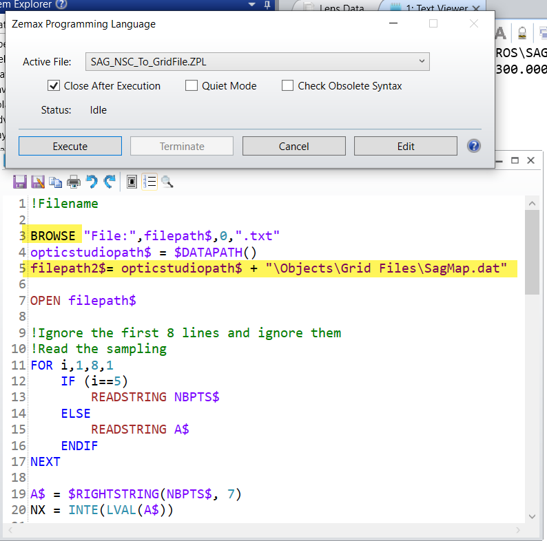
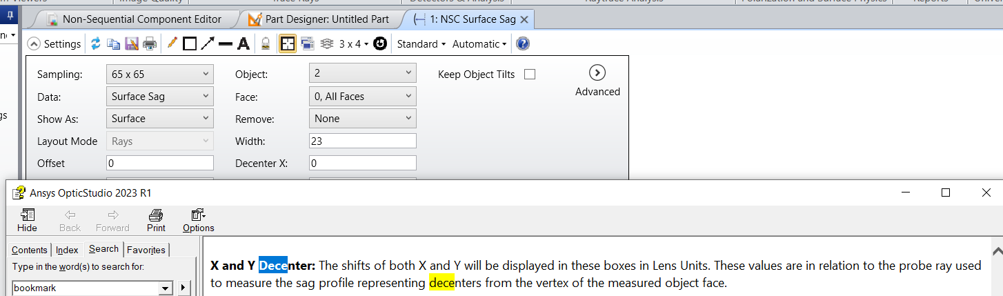
  1. How to import a CAD part file of windshield into sequential mode of zemax optic studio?  by the NSC sag tool, it only save the text file but not Dat format file, optical studio does not recognize it.
  2. if have sag data, how to convert it to xy extended polynomial surface or other freeform surfaces  which can be used in sequential mode of zemax optical studio/
  3. If have  mechanical layout of optical parts (step, STL files et al) developed by some mechanical design software such catia et al. how to import all parts into the sequential mode of zemax optical studio?  
  4. If have the global coordinates of each optical parts relative to the reference such as stop, is there a efficient and easy method to input the optical layout?  or can you recommend some other good methods for the layout?

Thank you.

icon

Best answer by Sandrine Auriol 18 April 2023, 17:35

View original

12 replies

Userlevel 6
Badge +2

Hi @OpticalResearch 

  1. For the NSC sag map, I have attached a macro that reads the text file of the analysis and converts it into a sequential file format that can be used for the Grid Sag Surface. The only thing which doesn’t work is that if the width of your file contains 4 digits, for example X_WIDTH = 1,000, the macro doesn’t read it properly. You have to manually change the file to 1000 (removing the comma) before running the converter. This could be improved using the API as the NSC sag map is now implemented in the API. 

  2.  

    If you have the sag data, my colleagues have shared some codes to show how to fit it to a built-in surface using the optimization tool. The post is here:

  3. You can’t import CAD parts into sequential mode. But you can make your system a mixed mode system by adding a NSC component surface. 
    https://support.zemax.com/hc/en-us/articles/1500005577002-How-to-model-a-mixed-sequential-non-sequential-system
  4. For your last point, I think I would use the coordinate return tool.
    Insert a surface and then after that surface insert a coordinate break that returns to the STOP surface, etc...Let me know if you need more details.
    There is an example here: 

I have written my answer a bit quickly so feel free to reply if any doubts. Thank you.

Hi Sandrine,

Thank for your quick response to my questions. 

I noticed some small programs was provided by people in the zemax forum. But it needs language programs such as matlab et al. For this we don’t have the language program. 

Maybe I want to ask a few more questions. You can help clear them in your convenience.

  1. In the using of the NSC Sag tool, is the setting about the decenter of x and y used to determine the center coordinates of the surface?  If they are zero, the symmetric axis cross center will be the surface center? 
  2. During the obtaining of the Sag Data of surface, what is the use of the point source which is set in front of the windshield? What is the distance of z of the point source for?
  3. Will the setting of coordinate system of the CAD part file affect the xyz coordinates of surface sag data?
  4. By the way, I attached a windshield sag data file (.txt format) converted by NSC Sag tool in zemax. Could you please help convert it for some freeform surfaces such as xy extended polynomial , biconic surfaces which optic studio can recognize?  And how to determine the normal radius et al?  Thank you very much and appreciated!

Best,

Bailin 

Userlevel 6
Badge +2

Hi @OpticalResearch!

Sorry I realized I never replied to your post.

We do provide scripts on the forum but ZPL (Zemax Programming Language) is included in Zemax and Python is an open source programming software. So that should allow you to work with those!

  1. The X and Y decenter settings are described in the help files in the latest releases of OpticStudio. Here is a screenshot:
  2. The point source is basically how we measure the sag. We follow this method: https://support.zemax.com/hc/en-us/articles/1500005487681-How-to-measure-the-sag-of-an-NSC-object. We send a ray and measure its length.
  3. Have you tried using the ZPL I sent?

Thank you very much, Sandrine.

Your this description is very helpful !

By the way, I tried the file but failed.  if you can give some description about how to use the ZPL file to transfer the sag data, will be appreciated. 

Best,


Userlevel 6
Badge +2

Yes sure. I have attached a text file that represents the text output of the NSC sag map.

When you run the macro, it will ask for a text file (so for example the one I have attached). This is the BROWSE command that I have highlighted.

Then it will create a grid sag file under "{Zemax}\Objects\Grid Files\SagMap.dat"


Let me know if that helps.

Thank you very much, Sandrine !  It helps.

Here, I want to ask your help or support for a multiple configuration setting for a specific HUD application. Why I ask you directly because I noticed one of your excellent articles about how to use zemax to design HUD in zemax website, although I can ask a random technical support from zemax.  Hopefully you won’t mind this.

Attached is my questions and please could you help me with that in your convenience!  


Best

Userlevel 6
Badge +2

Thank you for your comments! Glad the explanation for the macro helped. 

Yes sure, I have added two configurations to the article’s file. Let me know if that helps.

Hi Sandrine,

Your this file exactly solved my problems. Especially your setting of such a global reference surface is creative. 

Just one more question in the rotation of the curved mirror. In your file the curved mirror rotates around the x axis.  However, in practical cases, the rotation is usually not the coordinate axis. For example, if need to rotate around a specific axis or a line of cosine direction (-0.8, 0.2, 0.15), which passes the vertex of the curved mirror surface mirror.  Can you also show how to set such a pair of coordinate break surfaces for the curved mirror surface, which won’t affect other optical elements in the HUD system?    Thanks a lot.

Best

Userlevel 6
Badge +2

Hi @OpticalResearch 

If you enter the change on CB12, it won’t affect the other elements:

Is this what you mean?

Sorry I am not sure I understood.

Sorry to the question confused you much! Here I attached my questions again here.

Than you very much !

Best,

Bailin

Opps, forgot the attachments. here it is

Userlevel 6
Badge +2

Thank you for the detailed questions!

The YFIE operand in the multi-configuration editor may not be needed here. It controls the fields of the virtual image for each configuration. For example this operand controls the Y position of Field 1:
 

For the different drivers, I have updated the file but basically the height of the drivers can be changed with that parameter:


Let me know if that helps.

Reply