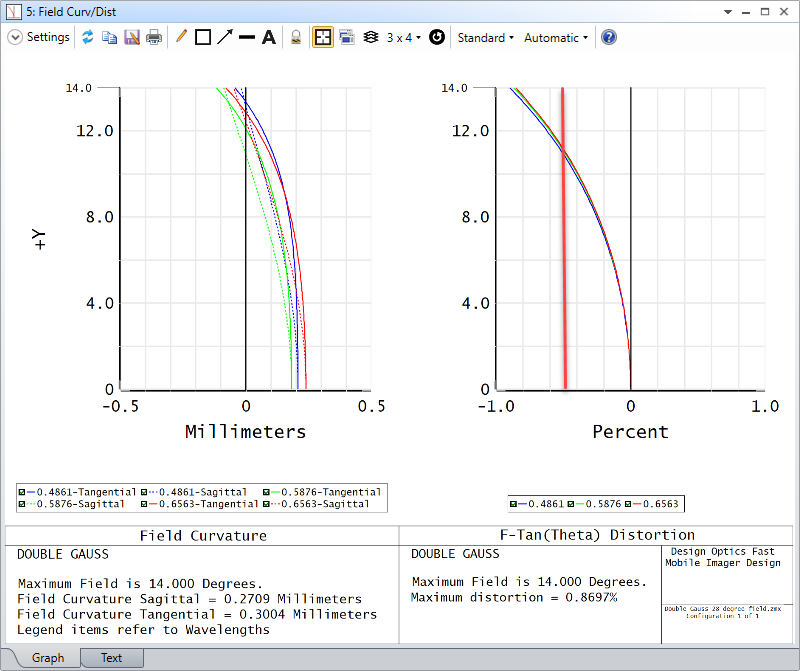
Hello All,
Supposed the definition of grid distortion is the position deviation on the image between chief ray and the centroid one for a specific field point.
Case one: In zemax, for the grid distortion, when select different reference field, why the grid distortion is different? What is the reference field used for during the plot of grid distortion?
Case two: In fact, if there is a rectangular field grid made of some grid points, given a stop aperture, there formed a grid image. The practical point image position of each field point deviated from their related chief ray position. Thus the real grid image is different from the ideal image, which also shows the grid distortion.
What is the different between case one and case two? It seems case two is very direct to the grid distortion. Why zemax uses case two? What is the advantage?
Thank you,


