I am modelling a laser position detection system. I wanted to know if OpticStudio comes with commercially available position detectors like quadrant detectors. If yes, any leads on how to find them in zemax. If no, how does one go about a situation where you have to use a commercially available detector in Zemax.

Solved
Quadrant Detector
Best answer by David.Nguyen
Hi Micah,
This is not a copmlete answer, but I don’t think you’ll find a readily available quadrant detector in OpticStudio. However, it could be simulated using 4 detectors. I tried my best with a dummy example using 4 Detector Rectangle:
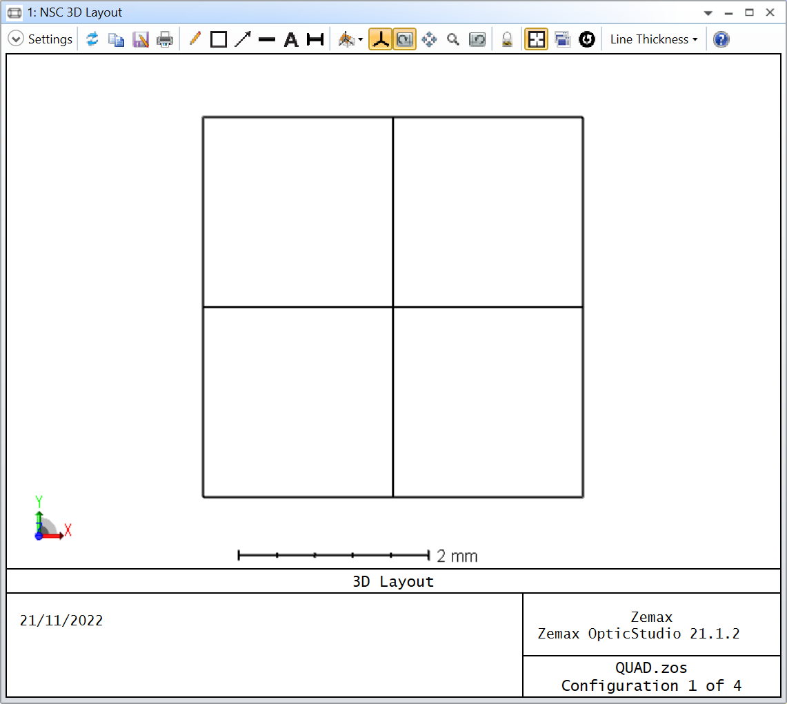
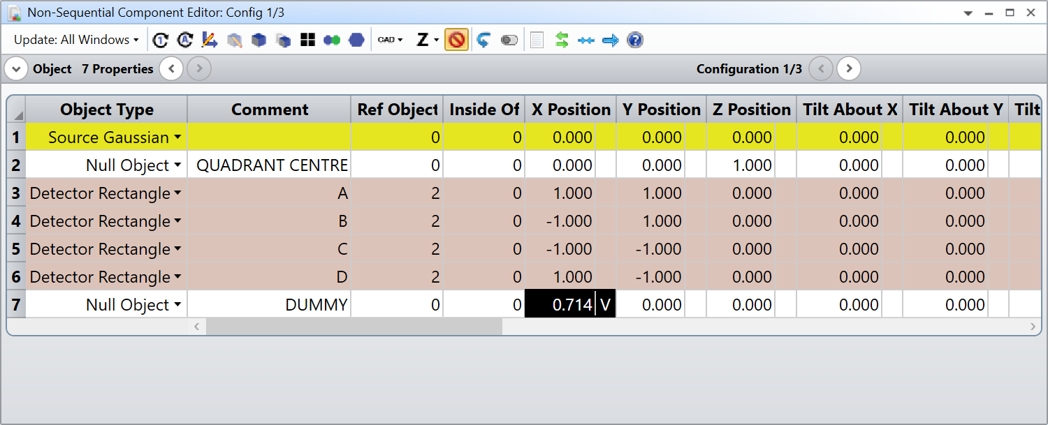
The Detectors are 2 by 2 mm (1 pixel by 1 pixel) and I’m using a Source Gaussian to simulate a 1-mm radius (1/e^2) laser beam. I will attach my file to my reply.
Then, I use the Merit Function and the NSDD operand to know how much power went into the four detectors. I made use of Eq. 1 and 2 from this article:
Developing Laser Spot Position Determination Circuit Modeling and Measurements with a Quad Detector
Except with my nomenclature, the equation is more like:
X = K * ( ( A + D ) - ( B + C ) ) / ( A + B + C + D )
Y = K * ( ( A + B ) - ( C + D ) ) / ( A + B + C + D )
Where A, B, C, and D are the flux reported by NSDD and K is a constant. I wasn’t too sure how to calculate the constant so I did the following:
- Add a dummy object, and set its X Position as a variable (it will be our constant K value)
- Add multiple configuration for the X and Y Position of the Source
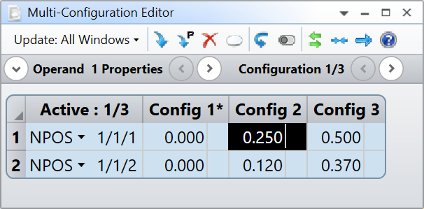
- Target the X Positions of the source in the Merit Function
- Verify the accuracy by reading the Y Positions
I’m sure someone more knowledgeable than me can explain you how to calculate what this constant should be. That being said here are the results:
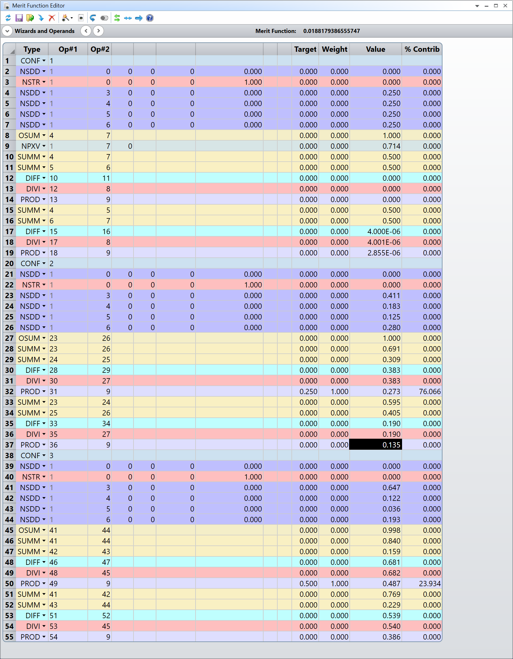
I let you decipher the Merit Function (and ask me about it if you don’t understand it), but the X coordinate is in operands 14, 32, and 50 while the Y coordinate is in operands 19, 37, and 55. For the X positions we have:
| X Target | X Reported |
|---|---|
| 0.000 | 0.000 |
| 0.250 | 0.273 |
| 0.500 | 0.487 |
For the Y positions we have:
| Y Target | Y Reported |
|---|---|
| 0.000 | 2.855E-06 |
| 0.120 | 0.135 |
| 0.370 | 0.386 |
The accuracy isn’t perfect, and I’m not quite sure why, but perhaps somebody else can chime in to give more advice.
Hope that helps somehow.
Take care,
David


Reply
Enter your E-mail address. We'll send you an e-mail with instructions to reset your password.
Need more help?
To Chinese users:
Do not provide any information or data that is restricted by applicable law, including by the People’s Republic of China’s Cybersecurity and Data Security Laws ( e.g., Important Data, National Core Data, etc.).
不要提供任何受适用法律,包括中华人民共和国的网络安全和数据安全法限制的信息或数据(如重要数据、国家核心数据等)。