Consider a plano convex lens used to focus a collimated gaussian beam , if the beam diameter is almost the same as the lens diameter (45.7mm) we get a geometrical rms spot size of 51um
if the entrance gaussian beam diameter is reduced to 20mm, we get a rms spot size of 4um because of reduced spherical Aberration :
but if the entrance collimated beam diameter is 150mm , which is 3 times larger than lens diameter we get :
Zemax reports a focus spot size of 2.2mm . Clearly this is not correct.
How do we model the propagation of Gaussian beam limited by an aperture. How would the diffraction generated by the circular aperture affect spot size? would the effects be negligible or would the spot size degrade of a truncated beam?
Best answer by Jeff.Wilde
@zak9000 I’m going to venture a guess that you are using a Merit Function operand, RSCE or RSCH, to calculate the RMS spot size. If so, there is an important detail to know.
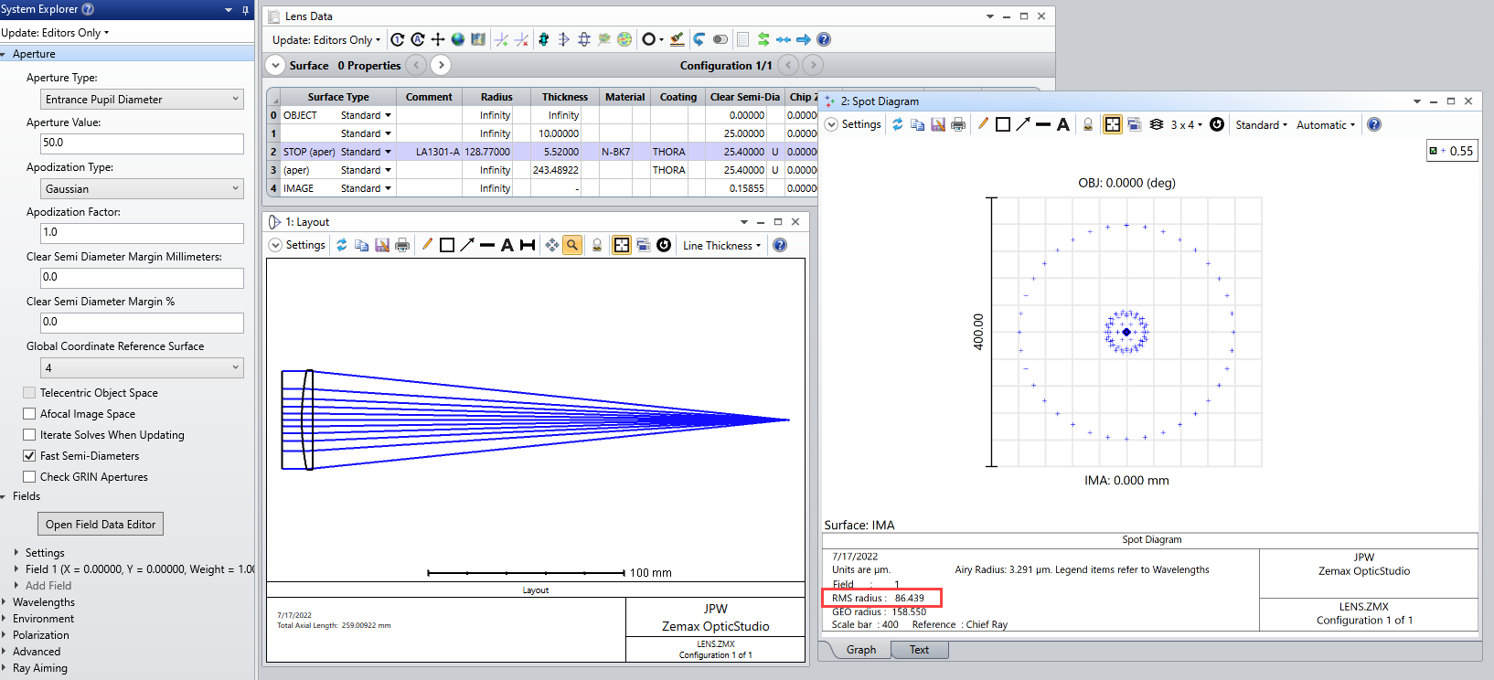
First, though, let’s just take a look at a simple plano-convex lens with a system aperture set by a user-supplied EPD, here it is approximately equal to the lens diameter:
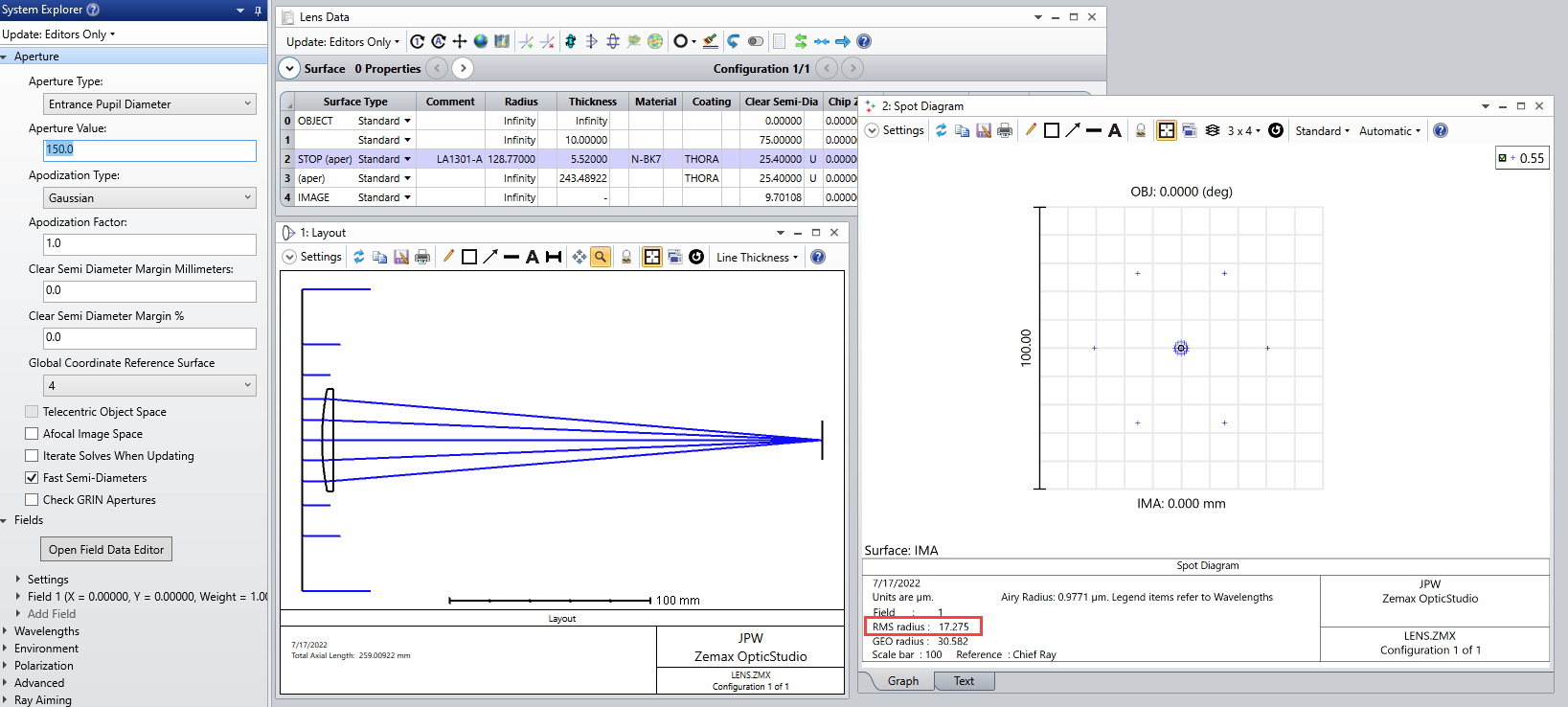
In this case, the spot diagram shows an RMS spot radius of 86.4 um. If the EPD is increased to 150 mm (three times the lens diameter), then the RMS spot size changes to 17.3 um:
Note the lens aperture blocks many rays and the RMS spot radius is computed using whatever rays from the defined spot diagram settings make it to the image plane.
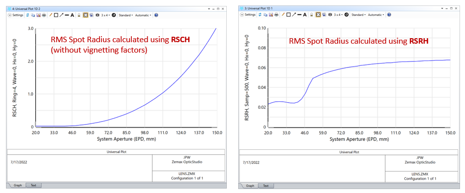
Alternatively, we can use a Merit Function operand to calculate the RMS spot radius. Let’s compare use of RSCH (based on Gaussian Quadrature) to RSRH (based on a grid of rays). Here is how the calculated spot radius changes with EPD for both options:
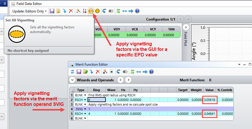
Not only are the shapes of the curves different, but look at the scale! How can this be? Well, it’s important to note that RSCH assumes an unvignetted circular pupil. This is the problem. When we increase the EPD beyond the diameter of the lens, then the system aperture is effectively being vignetted, but RSCH does not take this into account. Instead, the result using RSRH is the one to be trusted (assuming adequate grid sampling of the pupil is used). Alternatively, for a specific EPD value that is larger than the lens diameter, we can go to the Field Data Editor and apply vignetting factors to the aperture so that a resulting call of RSCH will yield the correct value. Or, even better, we can do the same thing in a more automated way via the Merit Function operand SVIG:
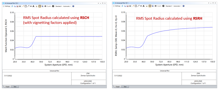
Now, we can re-create the RMS spot size plot using RSCH, but this time we will call it from the merit function *after* applying vignetting factors. In this case we find much closer agreement with the RSRH version:
Note the results are virtually identical for EPD values less than the lens diameter. For EPD values greater than the lens diameter there is some difference that can presumably be attributed to differing distributions of rays that actually make it to the image plane (but it’s not clear how meaningful the results are in this regime anyway). All of these results are, or course, based on geometric ray tracing. More detail can be found here: Impact of Vignetting on RMS Spot Size.
To account for diffraction, you can use the PSF or POP analysis tools and see how the focused spot changes as the lens diameter and/or incident beam diameter is varied. As Mark noted, there are Knowledge Base articles on these topics (or just refer to the help documentation).
@zak9000 I’m going to venture a guess that you are using a Merit Function operand, RSCE or RSCH, to calculate the RMS spot size. If so, there is an important detail to know.
First, though, let’s just take a look at a simple plano-convex lens with a system aperture set by a user-supplied EPD, here it is approximately equal to the lens diameter:
In this case, the spot diagram shows an RMS spot radius of 86.4 um. If the EPD is increased to 150 mm (three times the lens diameter), then the RMS spot size changes to 17.3 um:
Note the lens aperture blocks many rays and the RMS spot radius is computed using whatever rays from the defined spot diagram settings make it to the image plane.
Alternatively, we can use a Merit Function operand to calculate the RMS spot radius. Let’s compare use of RSCH (based on Gaussian Quadrature) to RSRH (based on a grid of rays). Here is how the calculated spot radius changes with EPD for both options:
Not only are the shapes of the curves different, but look at the scale! How can this be? Well, it’s important to note that RSCH assumes an unvignetted circular pupil. This is the problem. When we increase the EPD beyond the diameter of the lens, then the system aperture is effectively being vignetted, but RSCH does not take this into account. Instead, the result using RSRH is the one to be trusted (assuming adequate grid sampling of the pupil is used). Alternatively, for a specific EPD value that is larger than the lens diameter, we can go to the Field Data Editor and apply vignetting factors to the aperture so that a resulting call of RSCH will yield the correct value. Or, even better, we can do the same thing in a more automated way via the Merit Function operand SVIG:
Now, we can re-create the RMS spot size plot using RSCH, but this time we will call it from the merit function *after* applying vignetting factors. In this case we find much closer agreement with the RSRH version:
Note the results are virtually identical for EPD values less than the lens diameter. For EPD values greater than the lens diameter there is some difference that can presumably be attributed to differing distributions of rays that actually make it to the image plane (but it’s not clear how meaningful the results are in this regime anyway). All of these results are, or course, based on geometric ray tracing. More detail can be found here: Impact of Vignetting on RMS Spot Size.
To account for diffraction, you can use the PSF or POP analysis tools and see how the focused spot changes as the lens diameter and/or incident beam diameter is varied. As Mark noted, there are Knowledge Base articles on these topics (or just refer to the help documentation).