I got a problem in understanding the optimization in Zemax OpticStudio…
By doing a simple lens (with thickness T and radius of R1 and R2) and trying to optimize it on the spot image quality setting I don’t get the smallest RMS on the image plane. The optimal image distance of the smallest RMS after the optimization is always 1-2 millimetres after the image plane. Could someone help me to understand this? Why is it there and not at the image plane?
By testing I saw that changing the image quality option to contrast works way better to focus on the image plane…
I’ve added a simple model to show my problem…
Thank you in advice!
Page 1 / 1
The problem is, you are asking two different questions in your file.
The first question is being asked of the optimizer. For variable R1 and R2, and a fixed thickness T, what is the smallest spot size. The optimizer answers that question.
Then, you ask, at what back focal length L does the spot size itself minimize? That is at a slightly different L. The two are not the same: the best spot for given R1,R2 and fixed L is not necessarily the best spot for any L.
Make the back focal length variable, and add an EFFL operand to your merit function (or an f/# solve to the last radius) and you will get the optimum R1, R2 and L for that EFFL. Change the EFFL, and the spot will change.
So, the answer the optimizer gives is the answer to the question you ask, but not necessarily the question you meant to ask
Mark
In addition to Mark’s insight, I can provide a few thoughts.
After looking at the model, I see that the first lens surface is designated as the stop, while an additional aperture has been added to the second lens surface that is in fact the limiting aperture. In other words, the stop surface is not properly designated. The result is a lens that is intentionally vignetted.
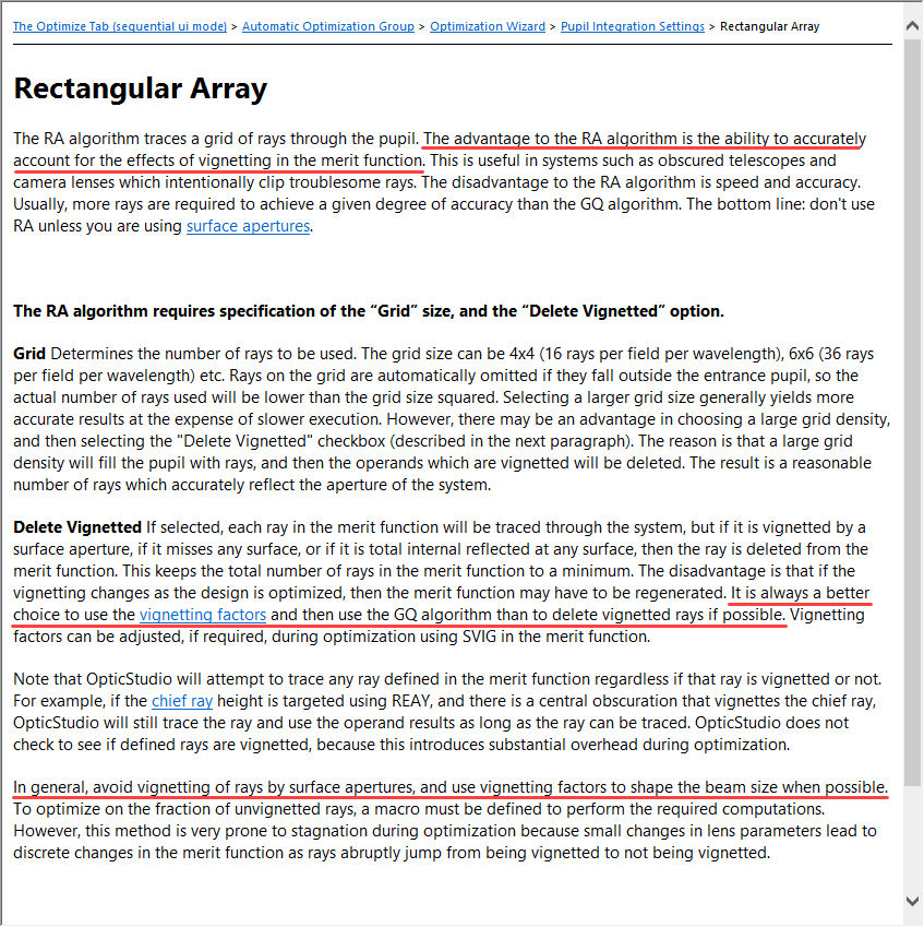
This has an important, but somewhat subtle, consequence for optimization. When choosing to minimize spot size, the user can select one of two pupil integration methods: Gaussian Quadrature (the default) or Rectangular Array. Note that Gaussian Quadrature does generally *not* account for arbitrary vignetting (unless vignetting factors are employed), although it can deal with the specific case of a central obscuration (which is not what is going on here). In contrast, the Rectangular Array approach can explicitly accommodate vignetting by removing vignetted rays from the merit function:
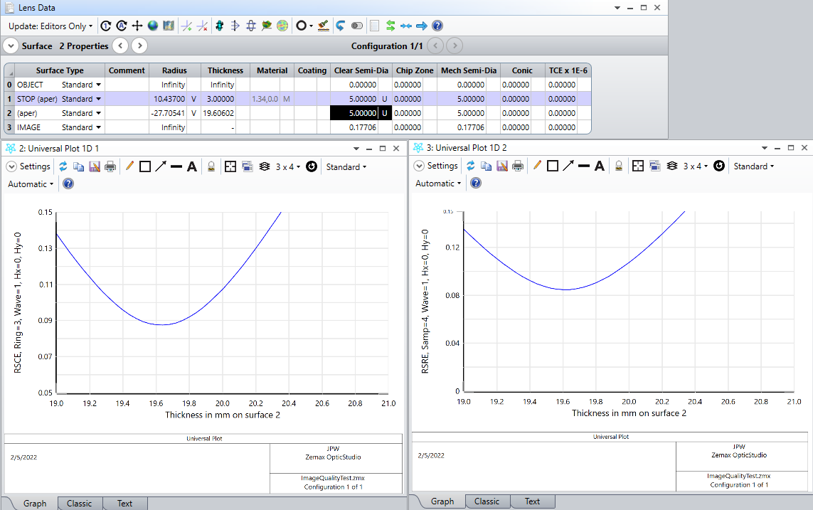
In the case here, Gaussian Quadrature was used, which effectively ignores the aperture on the second lens surface. So in the Layout window the resulting resulting spot size at the image plane appears not to be minimized. However, by simply increasing the aperture size so that the second lens surface is no longer the actual limiting aperture, you can see that the spot size is indeed minimized at the defined image plane (i.e., the amount of spherical aberration present alters the “best focal plane” location):
Also, it can be seen that the merit function value remains unchanged when increasing the second surface semi-diameter aperture from 3 mm to 5 mm, another clear indication that this aperture is being ignored during optimization.
This same limitation applies to the corresponding spot size merit function operands, RSCE and RSRE:
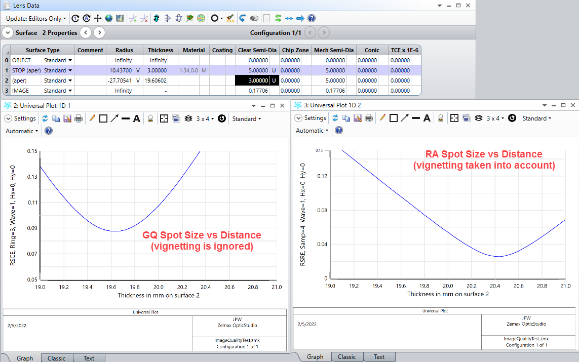
So, another way to see the impact of vignetting on the apparent focal plane location is to go back to the vignetted case (3-mm second surface semi-diameter aperture) and use these two operands in universal plots of spot size vs. distance from the lens.
We see two different apparent focal planes.
But if we eliminate vignetting by using the 5-mm aperture on the second lens surface, then the two approaches yield similar results:
This is a nice simple illustration of the impact that vignetting can have on lens design. The help documentation provides additional details: