I was wondering if there is a way to coherently sum POP results, for two different wavelengths, having used the POP “use polarization” option in both cases?
According to the OpticStudio user manual, page 1154, under “Use polarization” it says that “Because these 2 beams cannot be coherently summed, any complex field data for the output (i.e. real, imaginary, or phase data) will be set to zero.”
In my case I want to coherently sum the electric field information for Ex and Ey for two wavelengths. However, I am not sure if this is possible since the phase information is cleared at the end of the POP simulation when using “use polarization”.
Thank you in advance, Yannis
Best answer by Jeff.Wilde
Hi Yannis,
First, I assume you may know that the spatial interference intensity pattern between two beams having different wavelengths (frequencies) will oscillate at the difference frequency, which can very easily be outside the detection bandwidth of any realistic image sensor. The result is an image that is simply the sum of the intensities of the two separate beams (i.e., no detectable interference pattern).
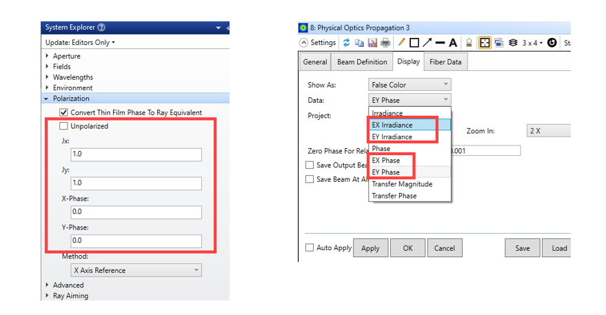
That being said, I think it is possible to get the field information you desire. Simply change the starting polarization state so that it is not unpolarized. You can then set the amplitudes and phases of the two polarization components. Now POP can provide the amplitude and phase profile for each polarization component for whatever wavelength(s) you desire. You would need to construct the complex field distributions and their sums outside of OpticStudio, say by transferring the results to Matlab. Alternatively, you can save the fields as ZBF files and sum them using the ZPL keyword ZBFSUM.
First, I assume you may know that the spatial interference intensity pattern between two beams having different wavelengths (frequencies) will oscillate at the difference frequency, which can very easily be outside the detection bandwidth of any realistic image sensor. The result is an image that is simply the sum of the intensities of the two separate beams (i.e., no detectable interference pattern).
That being said, I think it is possible to get the field information you desire. Simply change the starting polarization state so that it is not unpolarized. You can then set the amplitudes and phases of the two polarization components. Now POP can provide the amplitude and phase profile for each polarization component for whatever wavelength(s) you desire. You would need to construct the complex field distributions and their sums outside of OpticStudio, say by transferring the results to Matlab. Alternatively, you can save the fields as ZBF files and sum them using the ZPL keyword ZBFSUM.
thank you for the quick response! I will proceed as per your instructions. Admittedly trying to create a telecentric+spectroscopic Fabry-Pérot using POP is proving to be a bit of a challenge. I’m still trying to wrap my head around how neighboring dispersed wavelengths interfere inside my reflective detector model.
Hey Yannis, if you’re trying to model a Fabry-Perot Etalon, try using the coating feature to model the multi-beam interference. Look in samples/sequential/polarization fro a couple of examples.
Hey Yannis, if you’re trying to model a Fabry-Perot Etalon, try using the coating feature to model the multi-beam interference. Look in samples/sequential/polarization fro a couple of examples.
Hi Mark, thanks for the pointer, though the problem requires a POP approach. The issue is that we are detecting the photoelectrons inside the Fabry-Pérot, at a very specific location. To make things worse, the detector quantum efficiency of the detector is low, hence photons bounce between the pixel grid and the anti-reflection coating. In the JWST MIRI spectrometer this results in a large (30%) modulation, also known as fringing. The effect is similar to the example you mentioned, but it is more involved. Another complication is that the fringes depend on the part of the wavefront that is sampled, as the MIRI pupil is not homogeneously illuminated (our pupil is apodized, effectively). As such the fringes seem to vary across the PSF. In addition, we see a cruciform pattern on the PSF, which I am currently able to model thanks to the gaps in the pixel grid (hence the other Zemax ticket I posted a few days ago).
Long story short, I need to create a Fabry-Pérot model using glass surfaces, and manage to get fringes out. Fun fun fun.
The coating approach I suggested would work if you were interested in the Efield either before or after the coating, but you really want the Efield inside the coating/etalon. Is that correct?
The coating approach I suggested would work if you were interested in the Efield either before or after the coating, but you really want the Efield inside the coating/etalon. Is that correct?
Mark
Haha, I’m caught red-handed. Yes you are correct, I need the Efield inside the coating/etalon. Given the reflectivity of our anti-reflection coating, realistically we only expect 4 passes through the location of absorption:
Light passes through the anti-reflection coating and gets absorbed in the infrared-active layer (“AL”). We hope that the location of absorption is also the instrument focal plane (our detectors are on the thick side).
Light is reflected on the pixel grid that has narrow gaps and gets absorbed in the AL. Note that the beam is slowly defocusing.
Light reflects on the anti-reflection coating and gets absorbed in the AL. The defocus is largest here. We measure it in fact, our PSF is 20% larger than expected.
Light reflects a second time on the pixel grid and gets absorbed a fourth time in the AL.
The way I’m going about it is to first test a monochromatic case. Simulate the Efield at the location of absorption for each pass, and for each polarization state. For each polarization state I then coherently sum the bum files using ZBFSUM. I will then do an incoherent sum of the perpendicular polarization states.
Of course for a medium-resolution spectrometer, we’re talking about dispersed wavelengths interfering with each other (hence the observed fringing). As you can imagine, this is expanding the amount of calculations quite a bit :-) Based on Jeff Wilde’s comment though, I feel optimistic that I can pour the sweat and tears, and then coherently sum the Efield for many wavelengths, 4 absorption passes, and one polarization state, do the same for the other polarization state, and then sum the results incoherently…. That’s all in theory for now.