I have a simple model with one focusing lens and one coated mirror. I would like to find the correct OpticStudio way to decompose this model such that I can simulate the POP electric field, at a specific location inside the coating, without affecting the coating interference physics.
The coating itself represents an infrared detector. In OpticStudio I define it as a simple stack of four materials, plus an aluminium substrate for the mirror surface defined in the lens editor.
The ZnS material is the detector anti-reflection coating, followed by a thick pure silicon slab, followed by an absorptive layer of arsenic-doped silicon, followed by a thin pure silicon layer. Using the OpticStudio Coating tool “Absorption vs. wavelength” one can see that for a single incidence angle, the interference produces large amplitude fringes in the spectral direction. A similar result applies as a function of incidence angle.
Ideally, what I would like to do is simulate the POP electric field, for one wavelength and one polarization state (“use polarization” turned on), in the middle of the “SIAS” coating layer. Presumably, in order to do this, I need to redefine my model in OpticStudio, such that I can place a lens-editor layer at that location. However, I do not know how to do this in a physically consistent, OpticStudio-savvy way. I performed a simple test where I compared POP results for one glass silicon surface versus one coating of only silicon with the same thickness, and the results did not agree, presumably because no interference is modeled for glass. In my case, interference is a crucial aspect of the analysis, so any amount of help to understand interference modeling in OpticStudio would be appreciated.
Thank you in advance for your time, Yannis
Best answer by Hui Chen
Hi Yannis,
This is an interesting question. I considered this. In order to use POP to show the irradiance pattern at a certain location, you will need to define that location as a surface in the LDE. So if that location is within the coating stack, you will have to explicitly define these coating layers as optical surfaces in the LDE. However, I assume the one big issue here, as you have also noticed in your dummy test, is that in Sequential mode it’s difficult to simulate a Fabry Perot cavity effect because each bounce happening at an end mirror for the FP cavity will need to be modeled as a Mirror surface in the LDE, so for example 10 bounces between two end mirrors will then become 10 mirror surfaces defined in the LDE. So for a high finesse cavity where many many bounces occur, this approach of explicitly defining mirror surfaces repeatedly is not very realistic. This is the main reason why if you want to model the FP cavity transmission fringes effect in Sequential mode, it’s usually recommended that you use the coating to define the FP cavity instead of explicitly listing all these bounces as mirrors in the LDE. But in this case it also makes it impossible to use the POP tool. I though this over and couldn’t come up a good practical way of using POP to accomplish this.
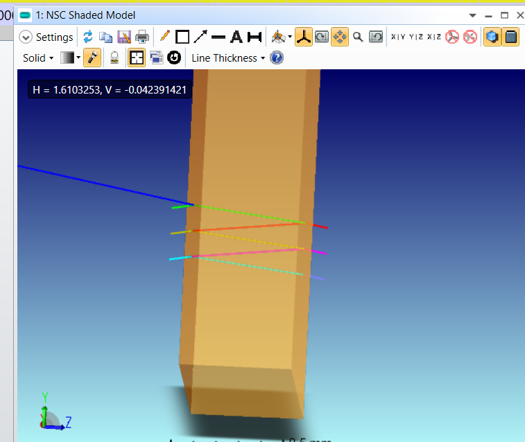
Alternatively, I was wondering if you could use Non-Sequential mode to model this FP cavity effect. The NSC mode is based on geometric ray tracing, but there is an option to show the Coherent Irradiance pattern on detector rectangle which models each ray as a plane wave so that certain types of interference fringes effect can be modeled. In NSC mode you can list these layers as rectangular volumes in the Non-Sequential component editor and place a detector anywhere you want without affecting the ray trace. You can also choose to save a ZRD file in which you can see the electric field distribution within the stacks. You can find some descriptions on how to use NSC to run coherent modeling in the following two KBAs:
This is an interesting question. I considered this. In order to use POP to show the irradiance pattern at a certain location, you will need to define that location as a surface in the LDE. So if that location is within the coating stack, you will have to explicitly define these coating layers as optical surfaces in the LDE. However, I assume the one big issue here, as you have also noticed in your dummy test, is that in Sequential mode it’s difficult to simulate a Fabry Perot cavity effect because each bounce happening at an end mirror for the FP cavity will need to be modeled as a Mirror surface in the LDE, so for example 10 bounces between two end mirrors will then become 10 mirror surfaces defined in the LDE. So for a high finesse cavity where many many bounces occur, this approach of explicitly defining mirror surfaces repeatedly is not very realistic. This is the main reason why if you want to model the FP cavity transmission fringes effect in Sequential mode, it’s usually recommended that you use the coating to define the FP cavity instead of explicitly listing all these bounces as mirrors in the LDE. But in this case it also makes it impossible to use the POP tool. I though this over and couldn’t come up a good practical way of using POP to accomplish this.
Alternatively, I was wondering if you could use Non-Sequential mode to model this FP cavity effect. The NSC mode is based on geometric ray tracing, but there is an option to show the Coherent Irradiance pattern on detector rectangle which models each ray as a plane wave so that certain types of interference fringes effect can be modeled. In NSC mode you can list these layers as rectangular volumes in the Non-Sequential component editor and place a detector anywhere you want without affecting the ray trace. You can also choose to save a ZRD file in which you can see the electric field distribution within the stacks. You can find some descriptions on how to use NSC to run coherent modeling in the following two KBAs:
for the specific detector I am working on, the anti-reflection coating reflectivity is such that we expect at most three reflections at that layer. Further reflections are not expected to impact our results drastically. As such, it may still work to model things sequentially.
That said, perhaps doing things non-sequentially is wiser. I will have to look into that. Since our optics a lot more complex than the basic model I shared, we still want to have the correct sequential wavefront incoming onto a non-sequential model of the detector.
I thought about this further and realized another big issue about modeling this FP cavity effect using multiple mirror surfaces defined in LDE in Seq mode is that in Seq mode rays do not split, therefore you will not see the interference effect if you follow just one ray path no matter how many bounces you model as mirror surfaces in the Seq LDE. I suppose you could try to create multi configurations in Seq with different configurations capturing different # of bounces, save the ZBF files and then coherently sum these ZBFs from different configs. However, the ZBF is centered on the chief ray, so if a ray comes into the stack at an angle, different bounces might lead to different chief ray location and you need to consider that when summing these ZBFs. In general it might not be a straightforward task to model this type of FP effect in Seq mode. This is the main reason why people usually use FP coating in Seq mode to handle this.
the approach you are describing (coherent sum of ZBF files) is what I’ve been struggling with. I tried determining the position of the chief ray for each configuration, and then decenter these in the POP tool. As you can imagine, this is a very blunt / inefficient approach, hence why I reached out to the Zemax community.
My primary concern now will be to see how well I can integrate the sequential optics of the telescope I’m studying with the non-sequential detector layers (modeled as volumes thus). For all I know this may be trivial. It is crucial, however, that the correct waveform be propagated to the detector, and through the detector volumetric layers.
since it is important to have the correct wavefront before entering the non-sequential etalon, could you suggest what would be the right way to combine the sequential optics of the telescope with the NS etalon? Indeed the goal is to see how the sequential unfocused POP beam before the etalon manifests as the coherent irrandiance + phase inside the NS etalon.