Solved

Pilot and Beam Width?

  • 17 November 2020
  • 4 replies
  • 759 views

What's the difference of 'pilot' and 'beam width' in the POP? 


In my simulation they are obviously different(with a factor of 2). Which one should be more accurate?


And I use GBPS operator to get the  w(1/e^2) of the Gaussian beam, it seems that it is very close to the pilot one:


what's the difference between the w from GBPS and w from pilot in POP? 


icon

Best answer by Csilla Timar-Fulep 17 November 2020, 19:08

View original

4 replies

Userlevel 5
Badge +2

Hello Xue,


Thanks for your question here!


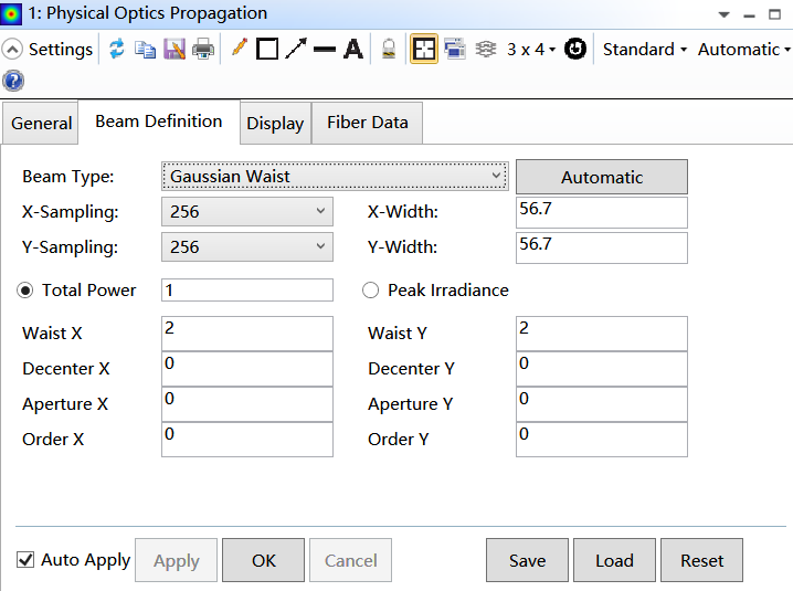
In POP you can see two different sizes indeed, one for the pilot beam and another for actual propagated beam. The pilot beam is an ideal Gaussian beam that is used to guide the actual beam propagated through the system (i.e. it is used to to select appropriate propagation algorithm and to calculate the Probing Rays and Transfer Functions). But the pilot beam is different from the actual beam itself.


You may find more information about the Pilot Beam in the Help files at: The Analyze Tab (sequential ui mode) > Laser and Fibers Group > About Physical Optics Propagation > The Pilot Beam.


Regarding the pilot beam size in POP and the GBPS operand, the GBPS operand uses the Paraxial Gaussian Beam tool. Although the pilot beam in POP is an ideal Gaussian beam, it is different from the Paraxial Gaussian Beam tool, because the pilot beam is propagated by real rays, while Paraxial Gaussian Beam uses only paraxial data when propagating beams.


You may find more details about the sizes in this knowledgebase article:


What is the size of my POP beam?


I hope this helps, but if you have further questions, please let us know and we will be happy to help!


Best,


Csilla


Csilla, thank you very much!    I think i've figured it out!

Userlevel 7
Badge +3

Hi


Here's how I explain this to myself, in case it's helpful. In sequential ray-tracing, the Optical Path Difference is computed relative to a reference sphere radius. Hence you might say that a system has a wavefront error of lambda/2 say, compared to a sphere of radius 50 mm. These are just made up numbers to show the scale length difference between the optical path difference of the wavefront and its bulk radius of curvature. 


In POP, we use the same trick, by propagating a 'pilot' beam, which is a best-fit Gaussian matched to your input distribution. That pilot beam is propagated using the Skew Gaussian code to give all the bulk properties of the beam as it goes through the system: are we near the beam waist, far from it, etc. The phase of the pilot beam is always spherical, as the Gaussian beam calculation is purely paraxial.


The POP phase is then the difference between the real phase of the POP beam and this reference phase. Again, this allows you to see the 'difference' signal of maybe a wavelength or less, compared to the bulk curvature of the wavefront.


So, think of the pilot beam as being the reference arm of an interferometer, and you interfere your real wavfront with it. What you see are the differences in phase, and this is that the POP phase shows.


Hope that helps,


- Mark

Thank you Mark! 


Although in my question I uploaded a POP plot of 'Irradiance X-Cross section' , you managed to explain the pilot beam in terms of 'Phase difference'. I didn't have a look at the POP phase before, and when I open it, it looks like:


I don't understand how to analyze the phase difference quantitatively, but when I set the Waist smaller(from 2 to 1), the phase difference becomes smaller too:


So this POP phase diagram shows how ideal the real beam is, i.e. the smaller Waist, the closer the real beam gets to pilot beam.

Reply