Solved

Physical Optics Propagation Phase Sampling


Badge

Hi all,


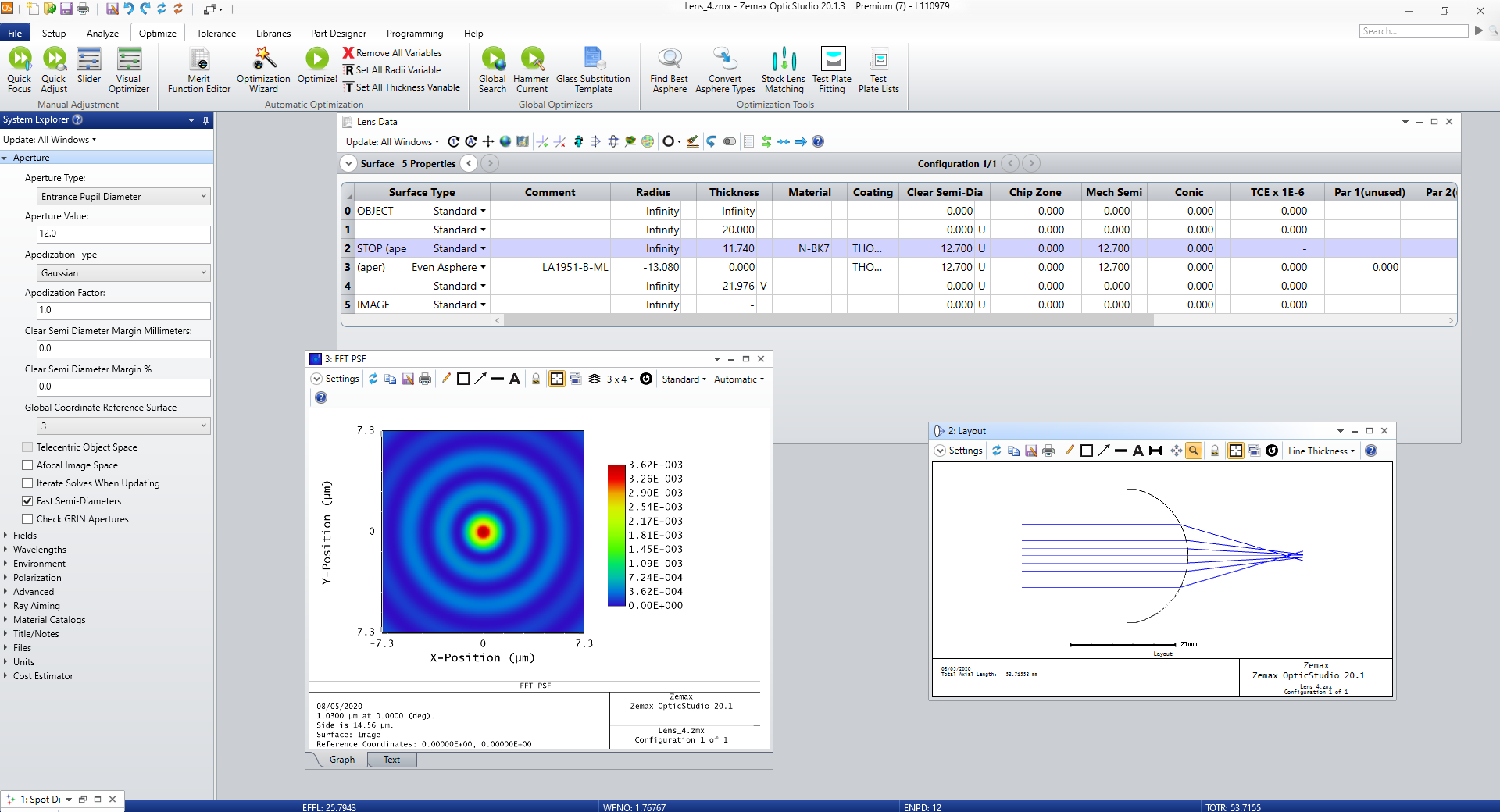
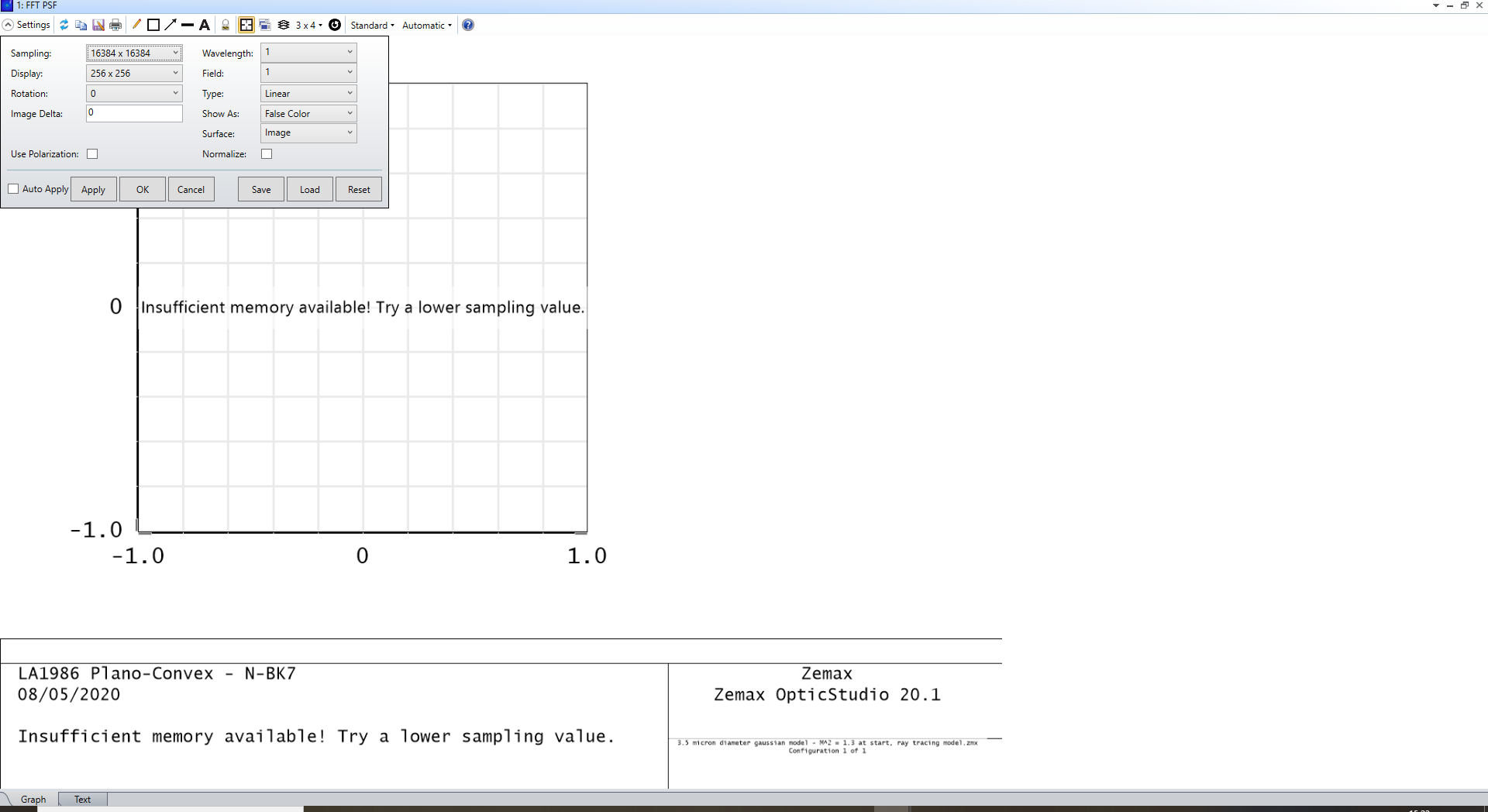
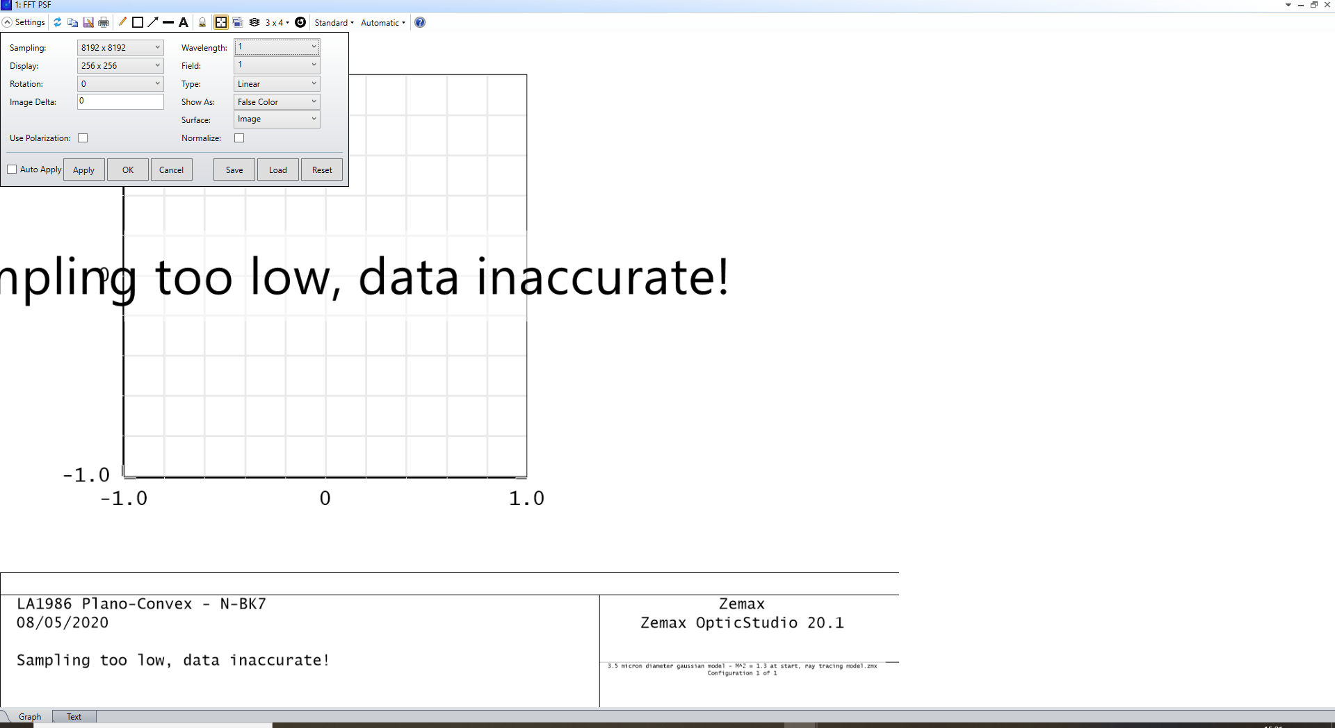
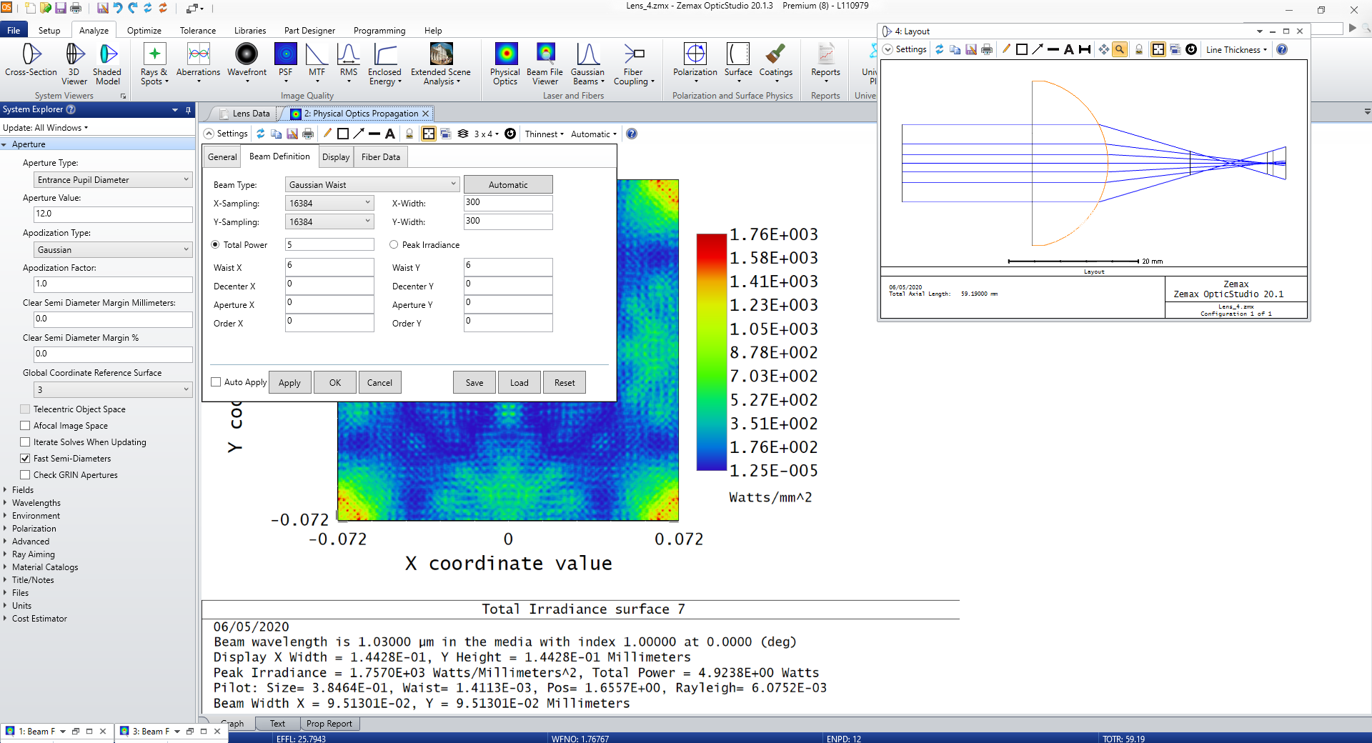
I have had a difficult time trying to model a 12mm collimated input beam going into a 25.4mm focal length plano-convex lens (LA1951-B-ML, THORLABS). Calculations indicate that I expect a focussed Gaussian spot of around 3.5 micron diameter. Having read through the 'Using Physical Optics Propagation (POP)' articles, I believe this is due to a phase sampling issue.
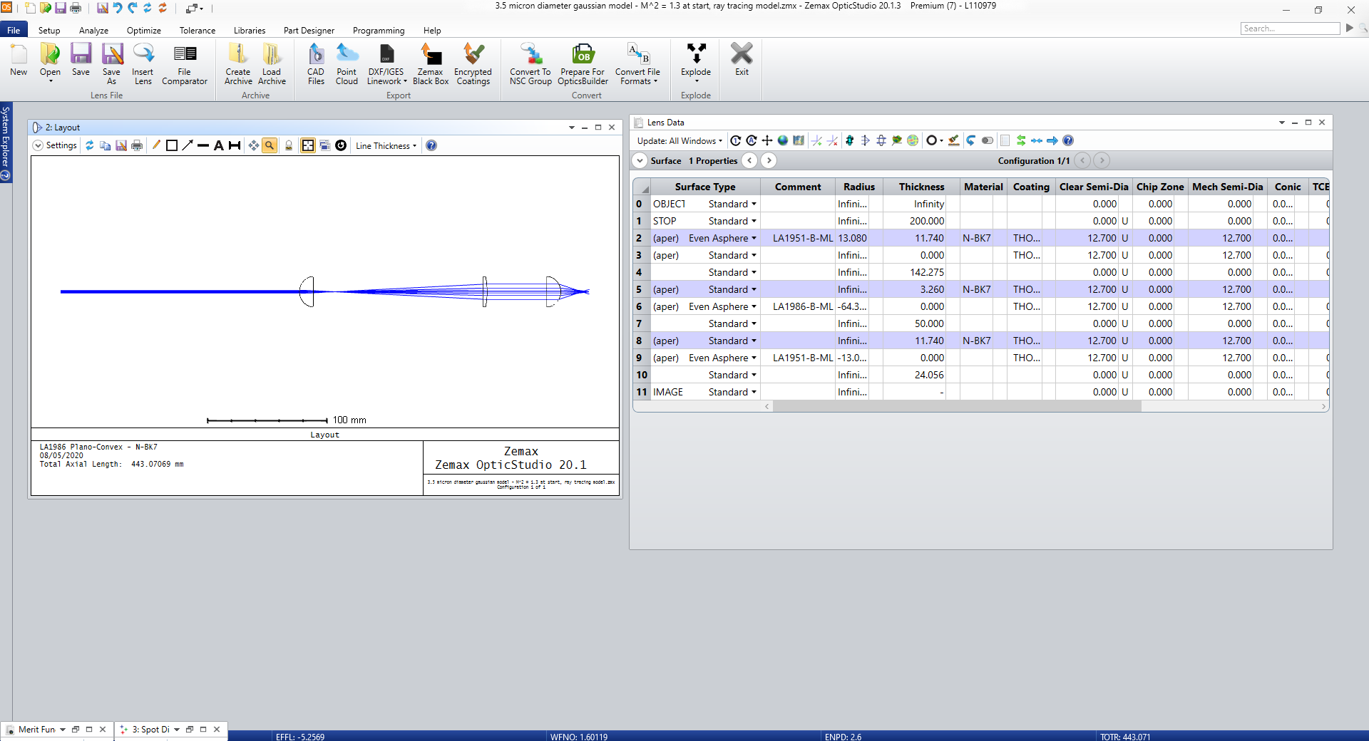
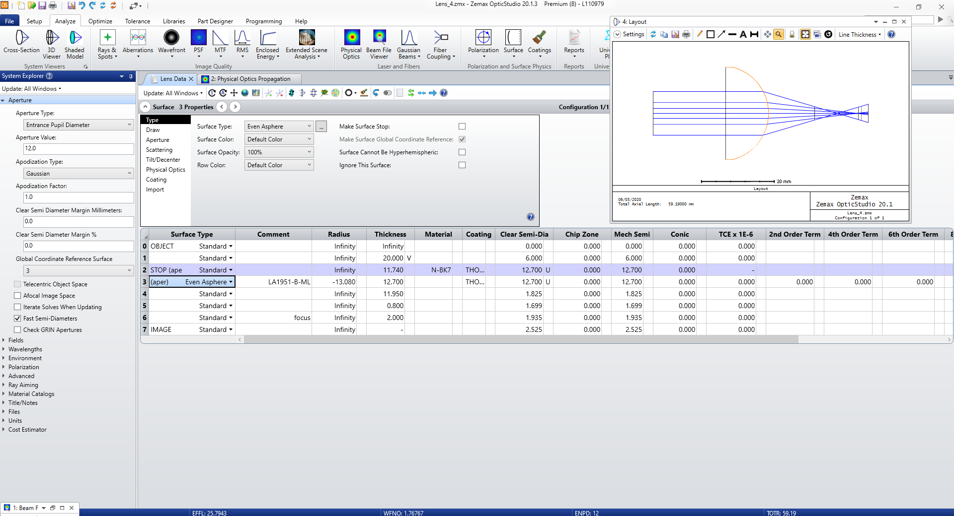

Setup


POP Settings - High Sampling


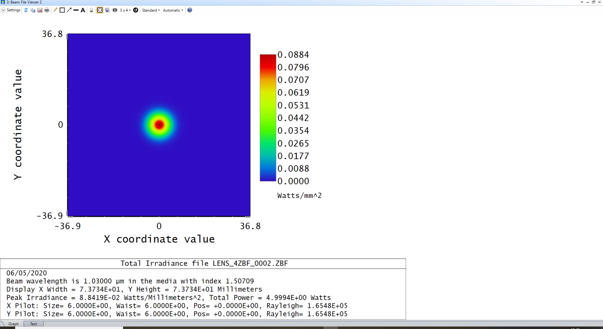
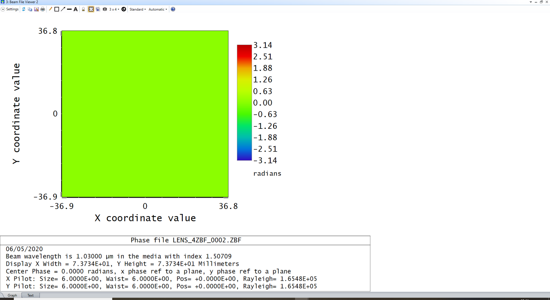
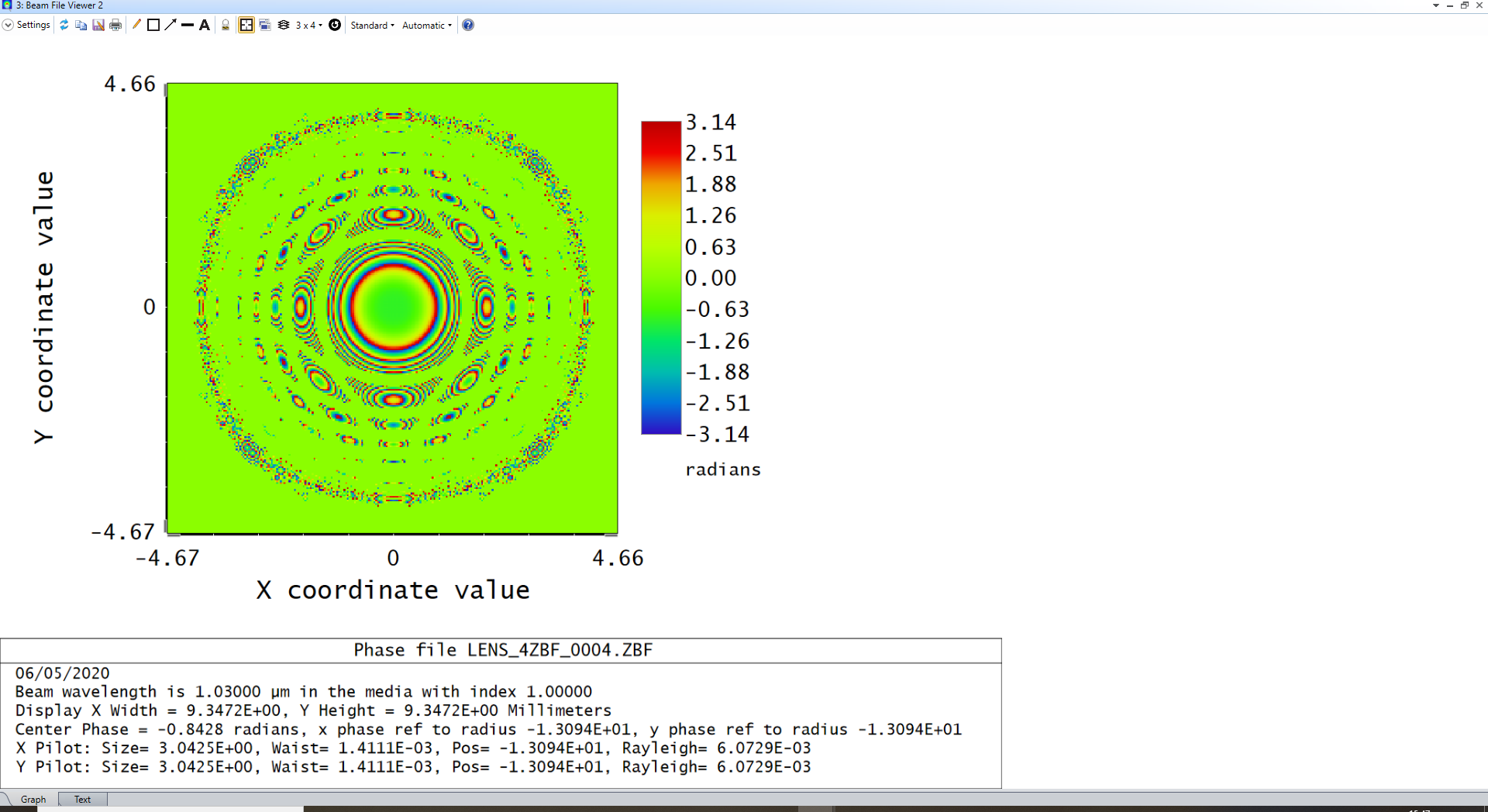
Upon running a highly sampled POP simulation, there is no phase difference across the incident beam from the free-space around it (at Surfaces 1 and 2).


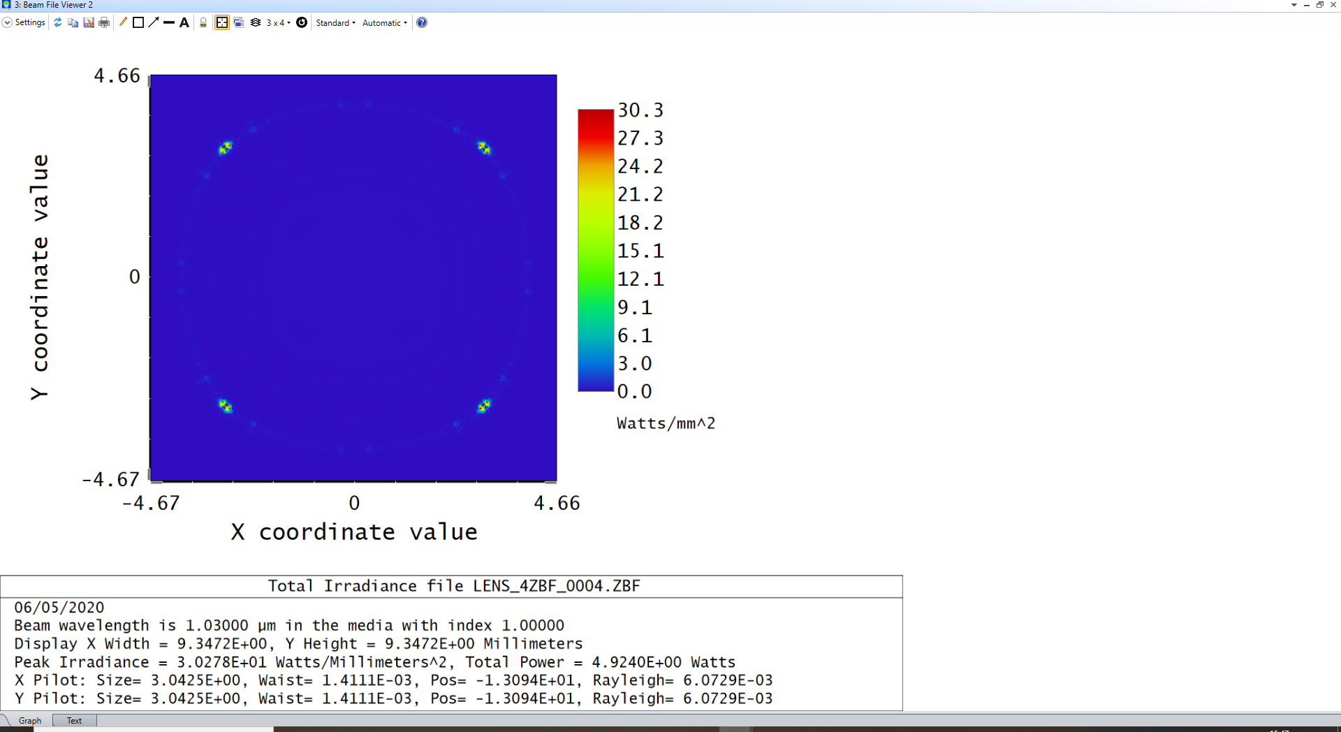
Surface 2 - Irradiance


Surface 2 - Phase


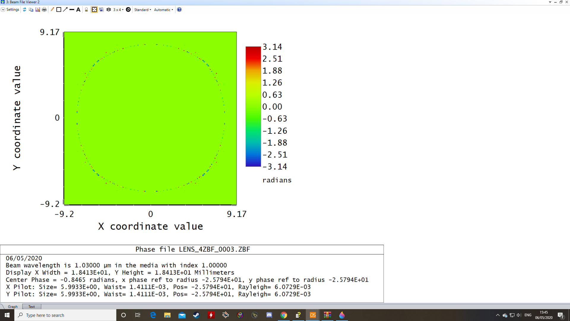
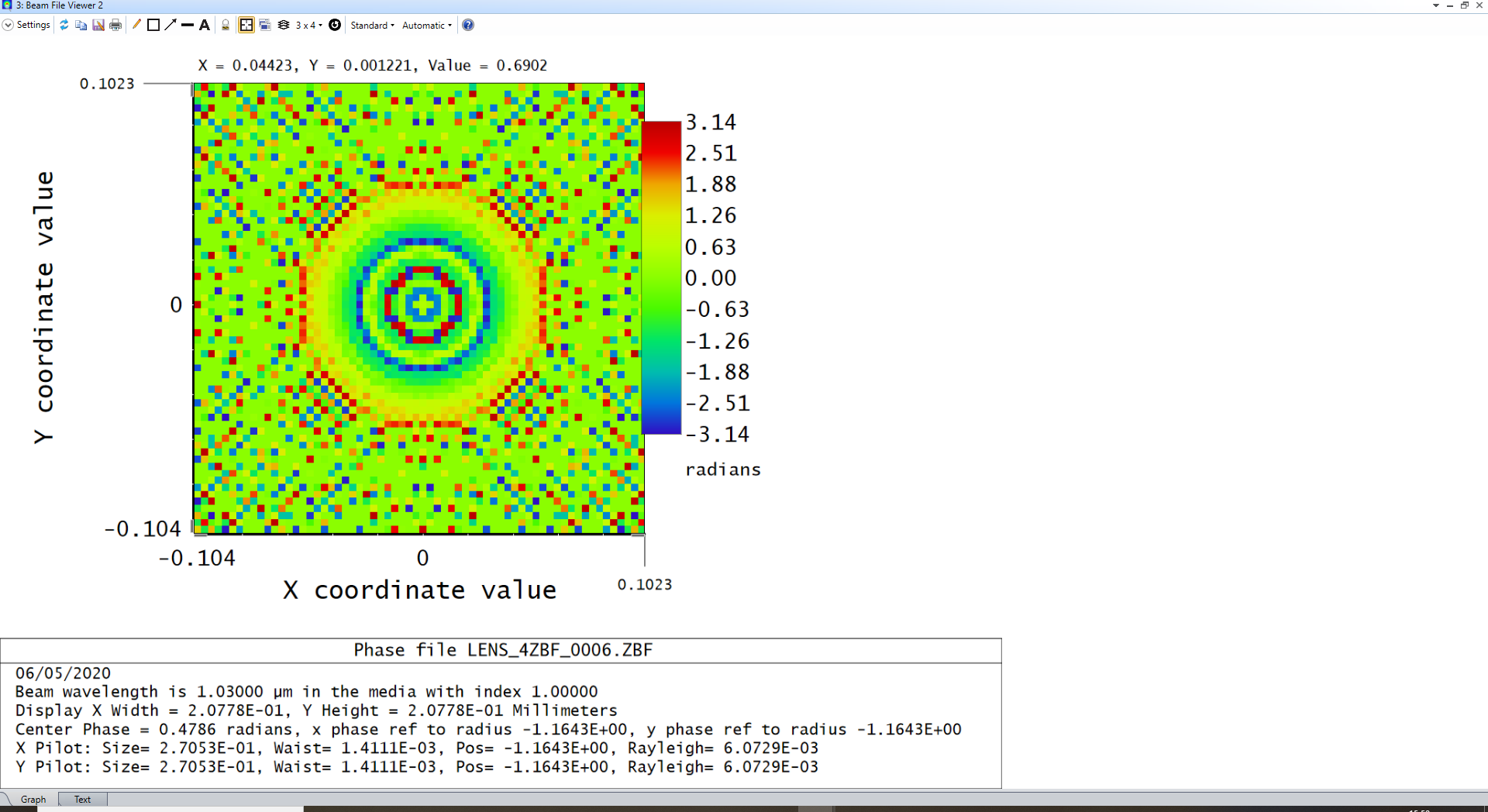
At Surface 3 (the curved lens surface) I observe a poorly sampled phase ring (aliasing), even while fixing the X-Y frame widths and using the highest default sampling rate.


Surface 3 - Phase (4x zoom)


This then cascades into the remaining surfaces, distorting the expected Gaussian profile of the beam.


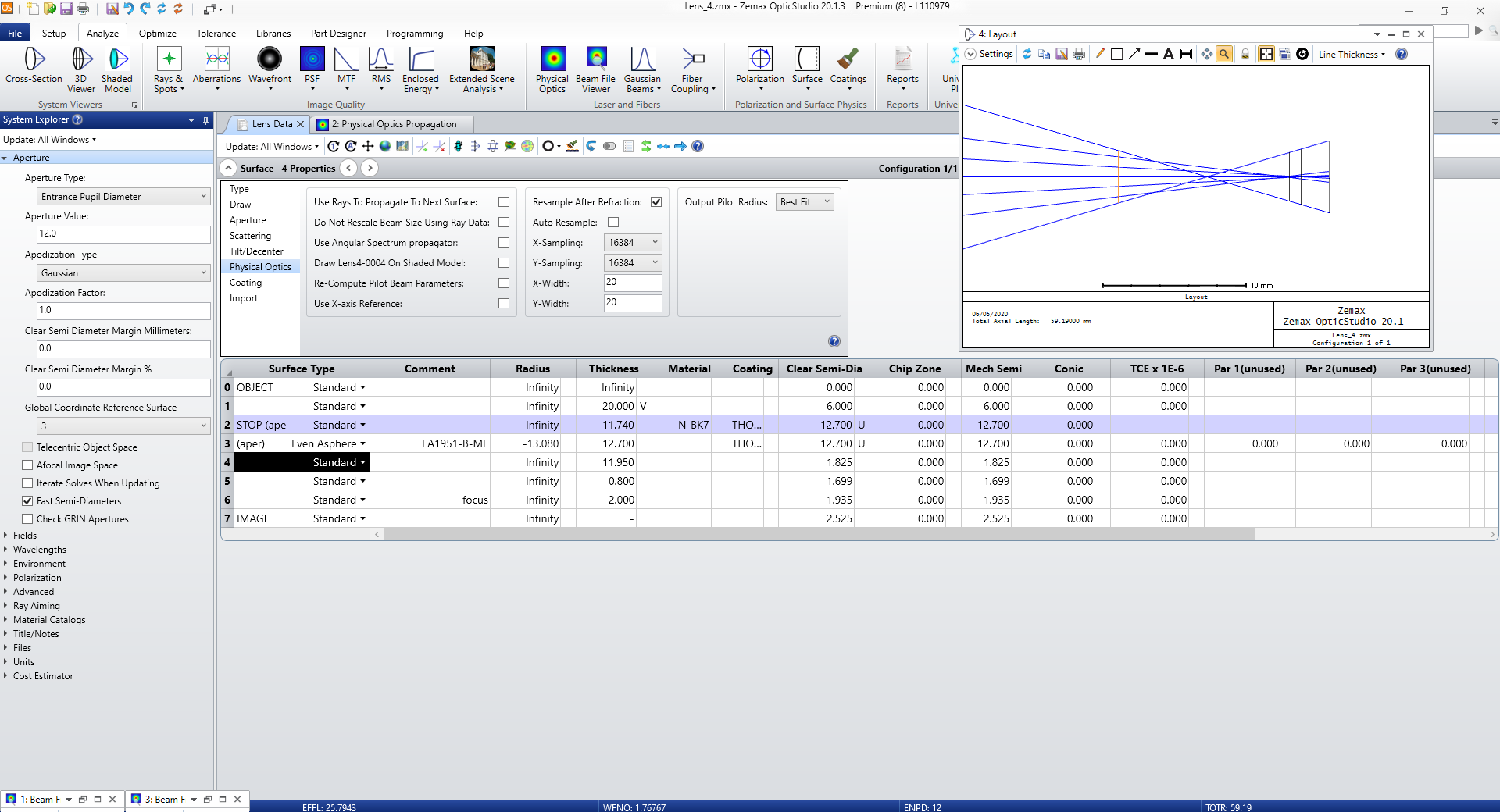
Surface 4 - Highlighted on Layout Tab


Surface 4 - Irradiance (4x zoom)


Surface 4 - Phase (4x zoom)


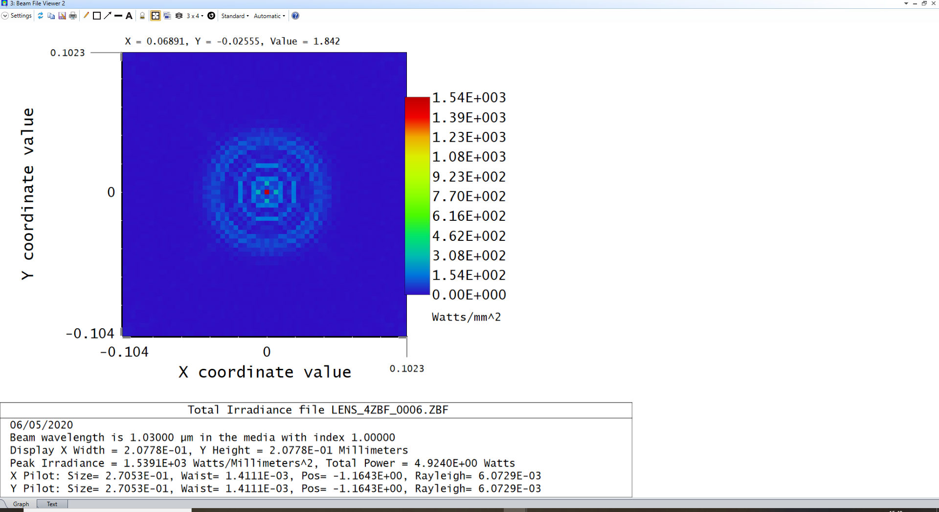
Surface 6 (Focus) - Irradiance (16x zoom)


Surface 6 (Focus) - Phase (16x zoom)


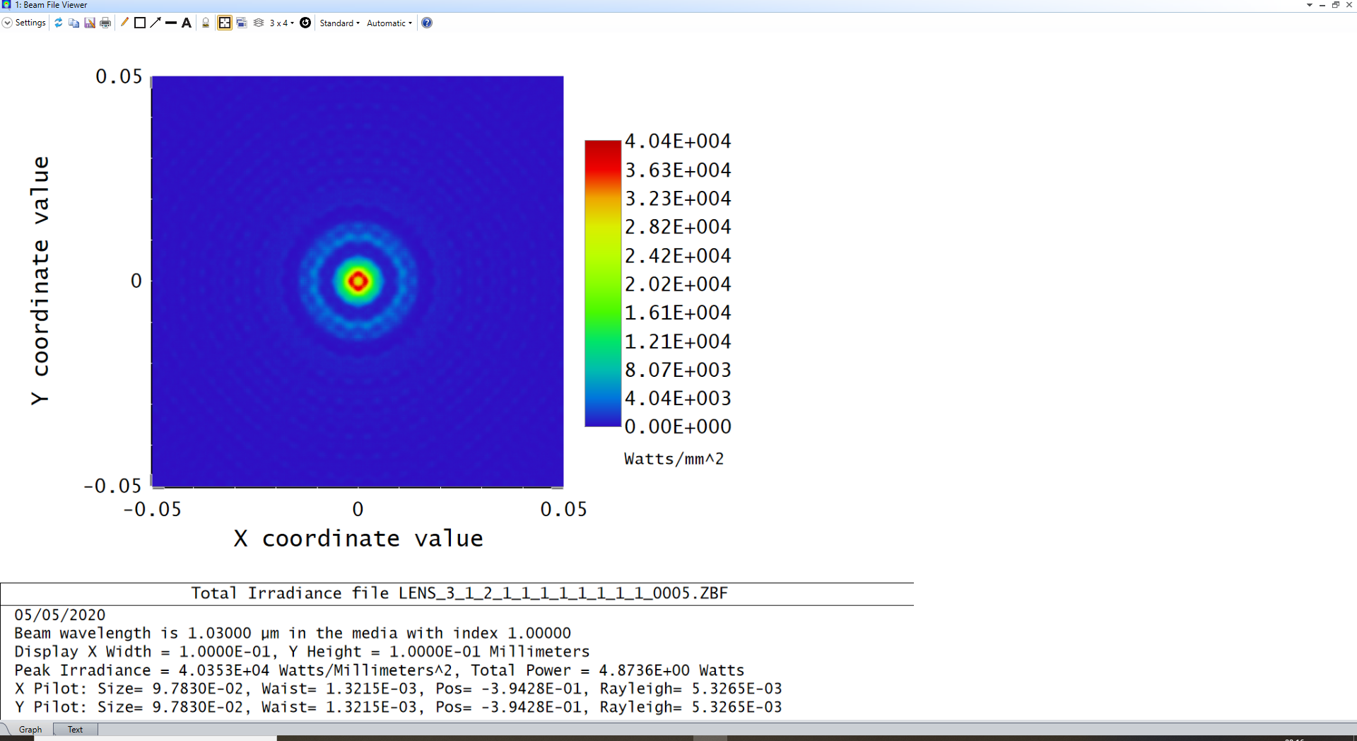
I have tried varying the frame widths at various surfaces throughout, but still cannot obtain a Gaussian beam shape at the focus due to the phase aliasing/interference distorting the beam. Even in previous trials where the irradiance profile at the focus has been processed at a highert resolution, similar distortion is observed.


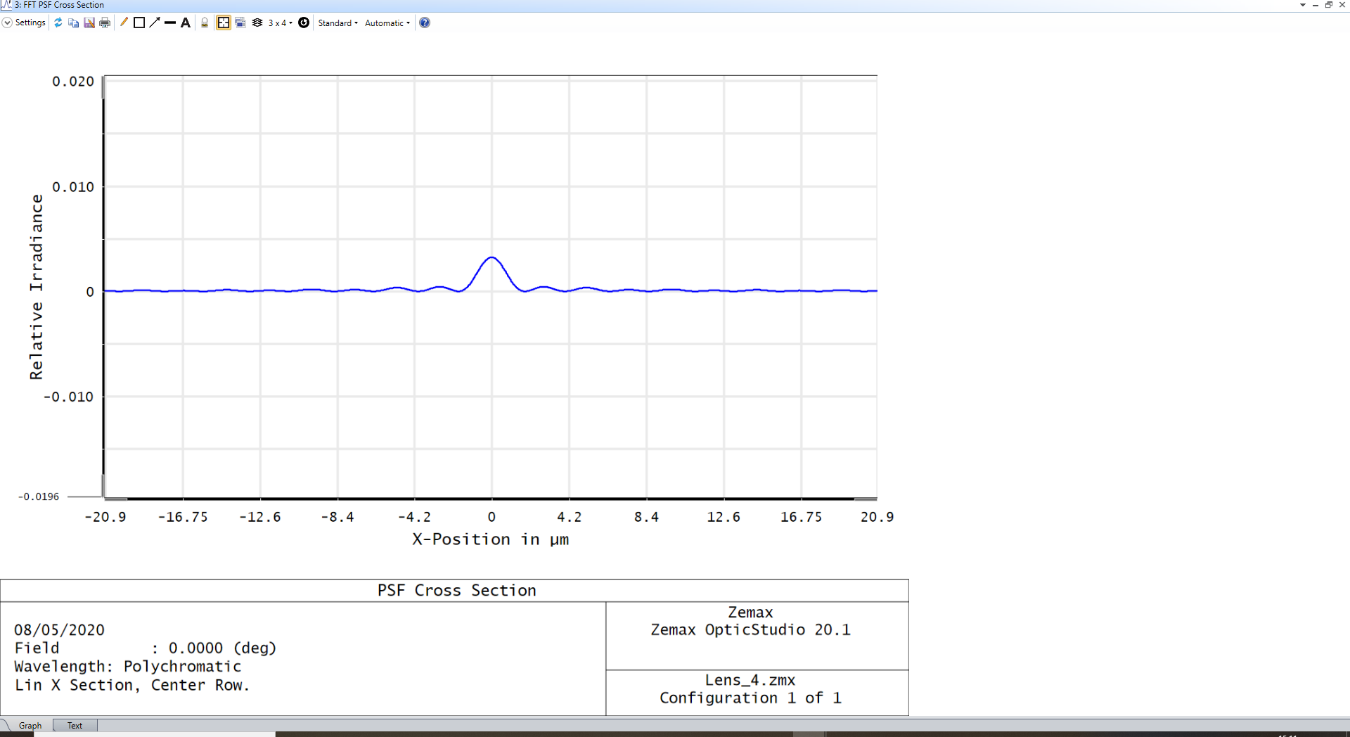
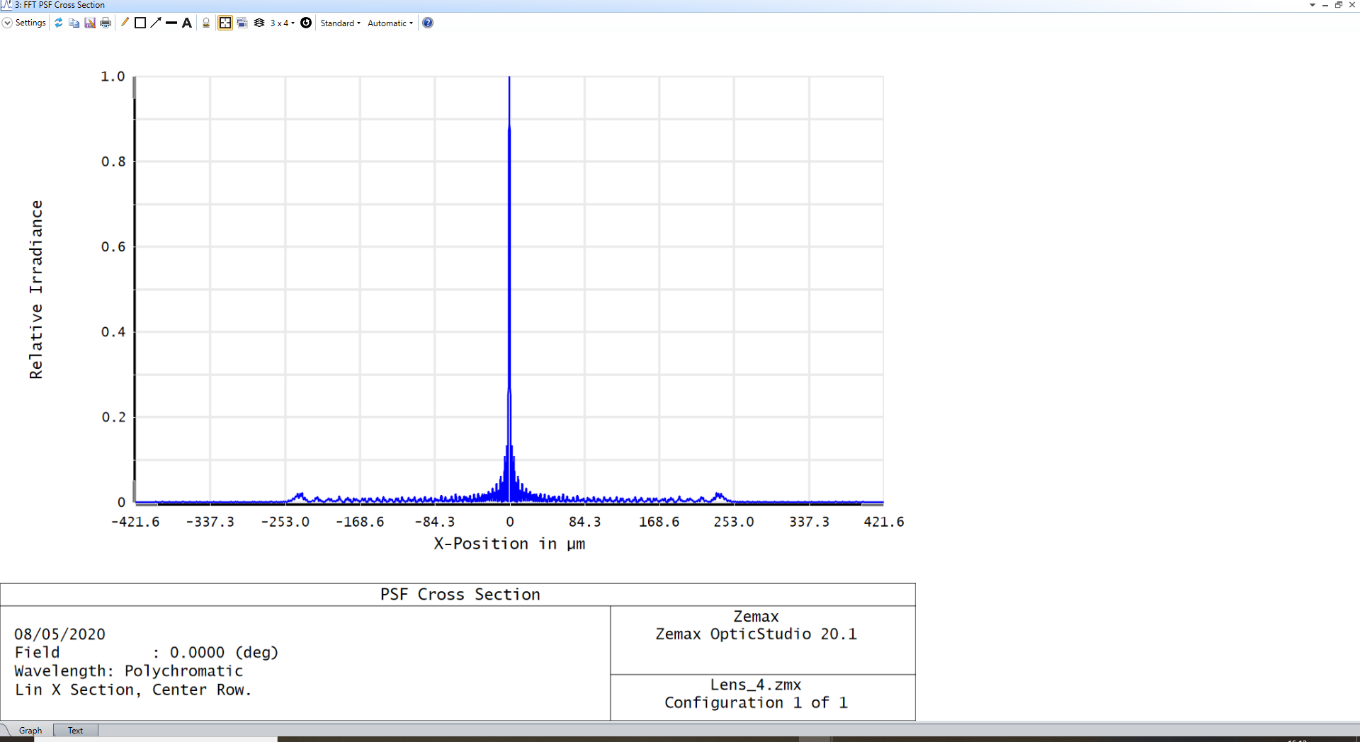
Beam at focus in a previous trial


Any help or suggestions would be appreciated.

icon

Best answer by Mark.Nicholson 6 May 2020, 21:36

View original

7 replies

Userlevel 7
Badge +3

Hey Don, the problem as I see it is that the lens is so dominated by spherical aberration that it will likely take a huge sampling to make POP accurate, and to what end? The geometric ray tracing will be perfectly accurate in this regime.


In general, it's hard to get useful work out of POP in the regime where conventional ray tracing is accurate. You should use POP in those cases where ray tracing is NOT accurate, and that is in the focus of a well-formed Gaussian or close to it. That's where rays predict an infinitesimal spot, but the beam actually forms a diffraction-limited waist.


What are you trying to accomplish with POP that ray-tracing doesn't give you?


Badge

Hi there, thanks for the quick response.


I tried using the 'Even Asphere' surface type to correct for the spherical aberrations, but it is still a potential issue due to the extent of it. I have previously used the POP feature to model a quasi-Bessel beam of approximately the same spot size (from a Gaussian beam input to a reimaged axicon setup), and it would be ideal to compare these with regards to the axial ranges that they maintain some portion of their peak irradiance values.


The input beam is of 1.03 micron wavelength, thus the spot size is getting near the diffraction limit. I have matched the surfaces on the Layout tab with where the focus will be in the POP simulation, both at the infinitesimal spot and just either side of it but the distortion effect occurs at all of them.


Thanks again for your time!

Userlevel 4
Badge +1

Hi Don. I've gone through your steps and gotten similar results (for time's sake, I used the 8196 resolution). I think Mark's answer still stands, that you're working in a regime where geometric effects will dominate. I did not detect that you were getting close to the diffraction limit. Running a spot diagram reveals that the beam is well outside the Airy disk. You are also working well past focus - another case for using the geometric optics option. But moving to the best focus does not change this in this case, as you are still working well outside the Airy disk.

Userlevel 7
Badge +3

Basically, if you can see the aberrations on the layout plot, don't use POP. Straight ray tracing will be accurate. You only need POP when the ray tracing overestimates the image quality by predicting a spot smaller than the Airy disk. And even in that case, the FFT PSF would be perfectly adequate for a system such as this.

Badge

Hi both,


Thank you very much for the clarifications. I have carried out a Fourier Transform on the image surface and I am getting around the correct Gaussian spot size. However, I do have a few follow up questions:.


The relative irradiance values it provides are extremely low - why is this? Once normalised it looks okay in the cross-section profile but prior to doing so it looks too low a signal-to-noise ratio to form a distinct Gaussian.


Unmodified


Normalised


Also, it appears to take the form of a Laguerre-Gaussian (2,0) mode. Is there anyway to modify this into the conventional/expected Hermite-Gaussian (0,0) mode?


Finally, this lens setup is actually a simplified version of the intended setp, which involves a 5x magnifying telescope prior to this lens. (Edit: The merit function when ran sets the distance between the object and the first lens to around 2500mm, but I have reduced it manually to 200mm in this image for illustrative pruposes).


Upon trying to run a FFT PSF at the focus here, the 16384x16384 sampling rate states there is insufficient memory available, while the 8192x8192 sampling rate states that there is inadequate sampling.


Thanks again for your time and consideration.

Userlevel 7
Badge +3

Hey Don,


You posted the .ZDA file, which is the data archive that contains all the data in windows that were open when the file was saved. We need the .ZAR (Archive) file to be able to see your file.


That said, from the screenshots, it all looks like we have been discussing. There is lots of geometric aberration, the Strehl ratio of the spot is very small, and diffraction calculations will struggle with any feasible sampling. Have a look at the OPD plot. How many waves of aberration are there?

Badge

Hi again,


Apologies for the mistake with the attachment!


The OPD plot for the complete setup (attached file) is below:


Thank you once again.

Reply