In sequential mode, is there any way to check % vignetting directly in the merit function? Currently it seems that I can only access it by opening the vignetting plot, but this is not useful for optimization or monte-carlo analysis.


For context, my application is tolerancing of a laser-mirror system. I would like minimized vignetting to be something I can base my tolerance compensator position on, as this represents beam clipping in the system. 


I think tolerance analysis in non-sequential mode would solve this problem, but I already have large body of analysis in the sequential version of the file, so I would like to keep it consistent, if possible. 


Thanks!
Can you use the system efficiency operand? IMAE.
Sean, can you be a bit more specific about what you want to do? I find it hard to see how vignetting will affect a tolerance analysis, given the scale length of most optical component tolerances. How big are the apertures of the components relative to the beam size?
IMAE ended up working for me. It's not 1:1 the same as vignetting, but it gave me an operand that characterizes beam clipping. Thanks, Matthew!


Mark,


More context on the problem: I am modeling small beam-steering mirrors in sequential mode. The path length between them is much larger than the diameter of the mirrors, and the laser beam diameter is relatively large, so misalignments in the elements were causing divergence, pointing, and (most importantly) beam clipping errors. I needed my tolerance compensators to respect the beam clipping as a figure of merit, but I wasn't finding a good way to do this before IMAE was suggested. 


Thanks, everyone!


I’m re-opening this topic...LMK if I should create a new one.

I want the systems I model to be free of vignetted rays and I want the apertures to avoid mechanically interfering with each other

In an off-axis, unobscured mirror system (e.g. TMA), it is common for folds to cause packaging issues.  So managing the angles of incidence of the chief ray as well as the size and locations of the apertures is critical.  Without sufficient constraints, a global optimization can create mirrors that overlap one another or curvatures that result in improvements in spot size, but only because rays were lost because they exceeded the aperture of the mirror.

It seems to me that IMAE will not produce a robust global optimization.  From the help file:

Optimization with this operand may not proceed smoothly if only hard-edged surface apertures, such as the circular aperture, are used. This is because OpticStudio estimates the derivative of operand values by making very small differential changes in the value of each variable, then computes a finite difference of the operand value.

Checking the results of IMAE against the Footprint diagram presents some challenges.  The Footprint diagram used to list the fraction of unvigetted rays.  This is not present anymore.  Furthermore, checking it with Relative Illumination is limited because this assumes a Lambertian source.  Checking it against the Vignetting Plot is also problematic because:

This feature is appropriate for rotationally symmetric lenses and fields, as only positive y field angles at primary wavelength are used in this calculation.

It seems to me that a series of operands may present the most reliable solution.  This is challenging. 

  • Is there an operand to test for vignetted rays?
  • Is there a better method to avoid vignetting?
  • Is there an operand to test to see if a ray escapes the semi-diameter?
  • Is there an operand to test to see if a ray escapes the aperture placed upon the surface?

 Hi @Brian.Catanzaro  - thanks for re-opening this topic! 

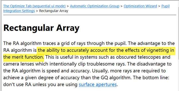
At this time, there is not a pre-provided optimization operand which reports the information you’re looking for. Typically, we recommend using IMAE as above or using an operand which uses the rectangular array method (rather than Gaussian Quadrature). In the latter case, this is because the rectangular array method is better for considering vignetted rays, as shown below:


If these are not robust enough for you, then the ZPL can be used to create an operand which performs the calculations you’re looking for. For example, in Sequential Mode, the ZPL provides several Numeric Functions for analysis of a ray trace with the RAYTRACE keyword. One of these is RAYV() which reports whether or not a ray has been vignetted:


In this case, you would launch a grid of rays and use RAYV to report back on the vignetting for a particular ray. This can be used to report total % vignetted, Additionally, other functions such as RAYX and RAYY can be used to report the landing location of a ray with respect to the semi-diameter of that surface. In the latter case, this could technically be done with a combination of REAY/REAX and DMVA operands in the Merit Function itself. Although if you’re working in the Merit Function Editor instead of the ZPL, you would require at least 2-3 operands per ray for this kind of calculation. 


Hey Brian,

You’re correct to quote the limitation on optimizing with IMAE that is given in the manual, but the same page gives the solution:

Optimization with this operand may not proceed smoothly if only hard-edged surface apertures, such as the circular aperture, are used. This is because OpticStudio estimates the derivative of operand values by making very small differential changes in the value of each variable, then computes a finite difference of the operand value. For the IMAE operand, a small change in the value of a variable may not change the efficiency estimate; if no rays are close enough to an aperture to change from being vignetted to unvignetted or vice-a-versa.

The solution is to replace hard edged apertures with soft-edged apertures placed on a user-defined surface. A soft-edged aperture has a transmission that is unity over most of the clear aperture, but near the edge the transmission drops to zero gradually over a small region, rather than abruptly.

Filter functions for doing this are included with OpticStudio as sample DLL files; see the “User Defined Surface” section of the “Sequential Surfaces” reference file for details. See in particular the discussion of the US_FILT4.DLL sample.
 

In addition to a user-defined surface, you can also use a Slide surface to position a bitmap on top of the surfaces of interest. This bitmap should have unity transmission over some area and then drop smoothly to zero over a zone that represents the edges of the component.

Remember to set ‘Use Polarization’ in the configuration file for IMAE so it responds to ray energy, and not ray quantity.

  • Mark


Reply