
Hi
I hope you both are well.
First of all sorry for tagging you both. I have seen couple of topics from you on PSF and its setups, and thought if i could reach out to you for help.
I am trying to characterise the performance of a collimator design (diffraction profile through POP) to high accuracy of setup 2 fields in a simple collimator lens design using an aspheric lens, and have few problems from probably very basic to a bit more challenging for me.
System details.
- The input a single mode gaussian output (considered perfect gaussian for this analysis) coming from either FC/PC or FC/APC (8 degree angle tilt: effective 3.71 degree) fibre. The fibre NA is 0.12 with MFD 5.3um.
- Wavelength: 780nm, aspheric lens with well corrected spherical aberration with wave front error <0.05 lambda.
Characterisation requirement:
- Firstly, I want to observe the beam profile at multiple distances away from the lens with high accuracy, down to ~10^-6-10^-8 irradiance level changes coming from beam truncation/diffraction at finite aperture and the fibre offset/ tilt further creating diffraction of the gaussian beam.
- I wanted to also observe the ellipticity of the beam arising again from the fibre offset from the axis of the lens.
- I have experimentally observed following.
- Elliptical beam
- Power of (-50dBm) at about ~5mm away from the main beam centre in the detector plane situated about ~150mm away from the lens, which i believe could be due to beam facing some aperture and hence i want to model it find the root cause since its a bit difficult to experimentally try that (given time and cost constraints for individual components).
Problems:
- I am having difficulty setting up on axis field by assigning the angle to the field it seems to also shift the beam as shown below. It seems to place the stop randomly in between (no surface present where beam width is same) even though with dummy surface i have tried to force the stop to be on the source to minimise the separation of beam.

- For just on axis filed (no angle), I have setup the POP and don’t see any warnings or errors in POP report. The resampling also looks fine. However, resampling the beam at surface 8,9 seems to somewhat change the beam profile. Below is the example, where i am setting the auto resampling at 8th surface. With and without resampling, i see a big difference, which would change for different apertures.
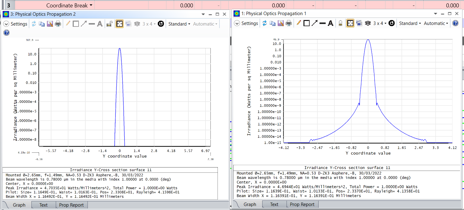
It changes significantly if i do resampling. Below shows for in 5mm : x/y widths for 1024x1024 vs 8192x8192 pixels
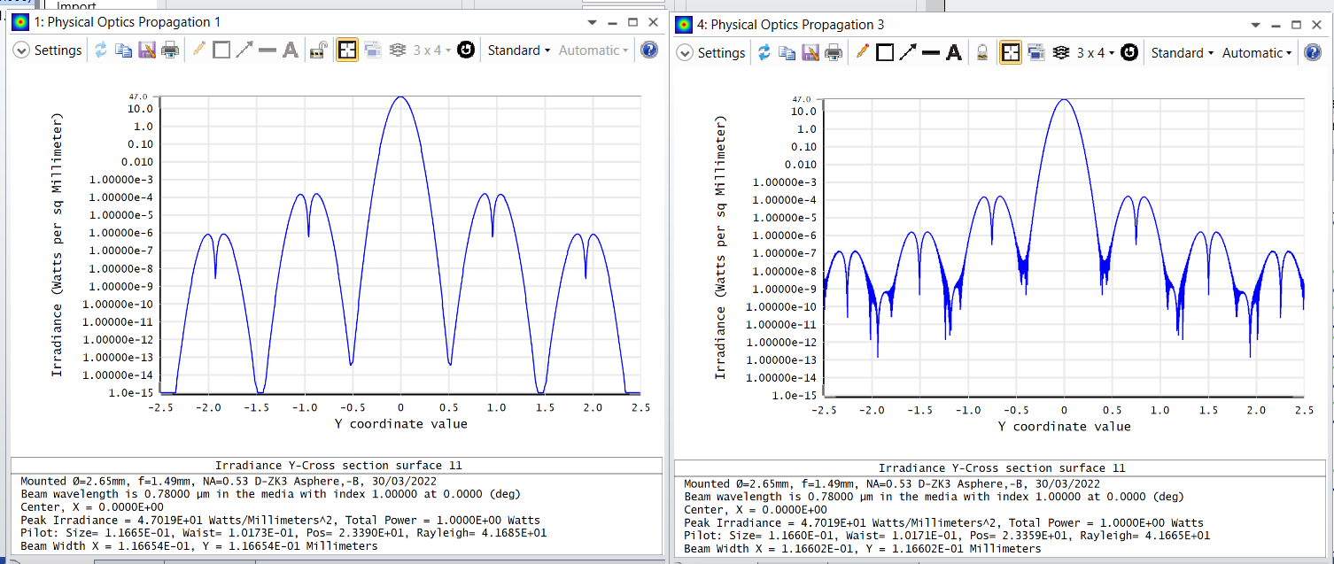
How do i decide my sampling of surfaces is appropriate to get trustable results.
- Since it would be easier for me to observe the beam profile in terms of angular spread, i would very much like to emulate this with Huygens PSF. I need some assistance for setup and establishing procedure for trustable simulation results.
The file size was more than 0.5Gb with above figures. So i have included the compressed file without these.
Regards,
Saurabh
