Solved

Nonsequential Mode: Coherent Optics, Problem with Detector rectangle and NSDC Operand

  • 19 October 2020
  • 21 replies
  • 1454 views

Userlevel 1

Hello,


I have a very simple nonsequential model:

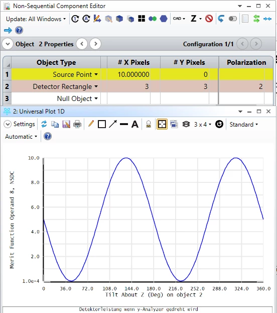
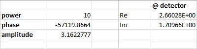
Source Point: power=10 W, coherence length=0, linear polarized: Jx=Jy=1, collimated light: cone angle=0

Detector rectangle: placed behind source, normal incidence, number of pixels=1, polarization=2 for measuring power of y-polarized light


Then I have a merit function:

NSDD for clearing the detector

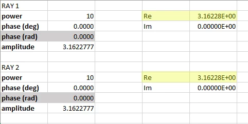
NSTR for making the rey trace

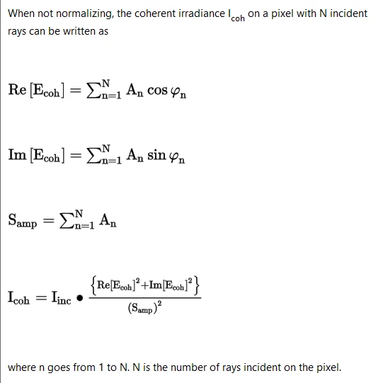
NSDC for measuring nonsquential coherent data


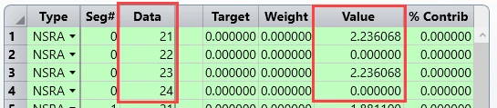
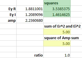
I was expecting to get Ey (y-component of the E-field vector), if I take Pix=0, Data=2 as parameters for NSDC.

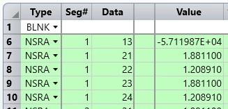
But I got 1,581 as result. From my understanding the result should be Sqrt(10)*cos(45°)=2,236. What's wrong here?


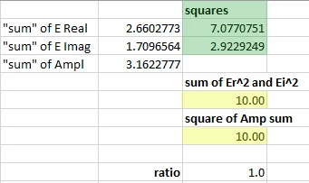
If I take Pix=0, Data=3 as parameters for NSDC I get 2,5 as result. Data=3 should calculate the power.

Because power is proportional to amplitude of E-Field vector and 1,581^2=2,5 this is consistent.

But according to Malus Law I was expecting to get 10W * (cos(45°))^2 = 5W.


I would be very happy if someone can help me clarifying this.


Thanks in advance and kind regards


Dirk


icon

Best answer by Angel Morales 22 October 2020, 01:42

View original

21 replies

Userlevel 7
Badge +3

Hey Dirk,


If you have Jx=Jy=1 then you should be launching 50% of the energy into each polarization state. It's best to save your data to a ray database (you don't need to trace many rays) and then use the Ray Database Viewer to see exactly what happens to each ray as it propagates.


- Mark 

Userlevel 1

Hey Mark,


I totally agree with you. 50% of 10W power should be 5W. But NSDC provides 2,5W instead.

What is also interesting: If I rotate the detector around z and plot the NSDC operand value against z-Tilt angle of the detector,

then I do not get a cos²(z-Tilt angle)-function.


I attached the zar.file. May be you can check what's wrong here.


Thanks a lot and best wishes

Dirk

Userlevel 5
Badge +1

Hi Dirk,


Thanks for your posts here! I've taken a look at your file, and I think there a couple of factors coming into play here.


For one, I realized that if I increase the resolution of your detector (I made it 3x3, so that the central ray still struck one pixel), the results matched your expectations (note that the NSDC operand is increased by one, as I added an NSDD operand for my own testing):


Another thing I noticed, though, had to do with how OpticStudio deals with computing the coherent power on a detector. In the Object Properties for the Detector Rectangle, there is a Normalize Coherent Power setting, which is checked on by default. Because of how OpticStudio has to handle coherence, it will take one of two approaches: (1) it will coherently sum the amplitudes of each ray on each pixel, then normalize the full power on the detector to match the full incoherent power on the detector (this is when Normalize Coherent Power is checked on), or (2) on a pixel-by-pixel basis, it will take a ratio of the coherent sum with the sum of the amplitudes for each ray, and multiply this to the incoherent power on that specific pixel (this is when Normalize Coherent Power is unchecked or when the detector is a single pixel). You can read a more thorough discussion of this in our Help Files at 'The Setup Tab > Editors Group (Setup Tab) > Non-sequential Component Editor > Non-sequential Detectors > Detector Rectangle Object'.


So, in the single pixel definition, I think there was some issue with the detector being a single pixel and how OpticStudio was handling the coherent computation. Interestingly, though, I don't quite get the same result when I have the 3x3 detector and uncheck Normalize Coherent Power. Regarding that, I think I will have to touch base internally and perhaps update our documentation after some feedback. In any case, I think modifying the resolution of your detector should be a workaround for now to obtain the total power as expected.


Please let us know how these thoughts work out for you, and thanks again for the question!


~ Angel

Userlevel 1

Hi Angel,


thanks for your support and your fast answer.


It is interesting that NSDC provides 2,5 W for the power on the detector, which is wrong, whereas the detector viewer shows 5 W coherent irradiance, which is right, even if the detector just consists of one pixel.


By the way: I found another workaround. I have just put a Jones Matrix as y-analyzer before the detector (with Pol. flag = 0). This works even if the detector just has one pixel.


Best wishes and happy simulating


Dirk

Userlevel 6
Badge +4

I am also interested in this discussion. I find the computation of coherent power very confusing. I attach a modified version of Dirk's model. In this version I added  a second source which sends a ray parallel the first into the single pixel detector. In this case, both sources have y polarization, but the second source has a phase of 180 degrees. A ray database shows what we expect: At the detector the two rays have E fields only in the y direction and they are oppositely directed. In the real world the E field would cancel and we would have zero power on the coherent detector. (And we would reconcile that with the power of the two sources by tracing the plane waves back to the sources and note that the combined sources had zero emission.)


But the details aside, I would think that any calculaton of coherent power at the detector would recognize that E fields sum and that zero E field means zero power.


Kind regard,


David

Userlevel 6
Badge +4

Here is the ZAR for above.

Userlevel 7
Badge +3

Hi David,


This is a complicated area not given easily to quick answers. The first place to start is the manual, as ever. See the Help under The Setup Tab > Editors Group (Setup Tab) > Non-sequential Component Editor > Non-sequential Detectors > Detector Rectangle Object.


Here are the salient pieces, but I recommend reading the whole thing:


Comments on coherent data computations


The propagation and interference of light generally has properties of both particles and waves. Rays can be thought of as the particle representation, and diffraction interference (such as for a diffraction PSF) can be thought of as a wave representation.


For NSC analysis, OpticStudio uses ray tracing to determine optical paths and energy distributions. OpticStudio accounts for the phase along the ray, and this allows for computation of some interference and diffraction effects. However, it is important that the user understand what assumptions the model makes and how these assumptions affect the accuracy of the results.


When a ray strikes a detector, OpticStudio computes the real and imaginary parts of the electric field by using the intensity and phase of the ray referenced to the center of the pixel struck. The real and imaginary parts may then be summed for many rays that strike the same pixel. OpticStudio also sums the intensity (amplitude squared) for each pixel.


Note from Mark: Note referenced to the center of the pixel struck. David, in your case if the two rays land on different parts of the single pixel, we still have to compute the phase relative to the center of the pixel to be able to add them.


Because the phase is accounted for, some rays will constructively interfere with other rays while other rays will destructively interfere. This allows OpticStudio to simulate effects such as fringes in interferometers (shearing or otherwise) or interference from various orders of a diffraction grating. However, computing the coherent irradiance involves some assumptions. Physically, destructive interference means the energy would have propagated somewhere other than where the ray went. In a similar way, when constructive interference occurs, the squaring of the amplitude sum of many rays artificially and nonphysically increases the energy in the beam. OpticStudio cannot determine where the energy went (or came from), and therefore cannot account for conservation of energy in coherent irradiance calculations without making assumptions. OpticStudio can make one of two different assumptions: either to normalize the coherent power on the detector to match the incoherent power, or to determine the coherent power using the incoherent power on each pixel and scaling by the degree of coherence of rays landing on each pixel. Which method is used depends upon the number of pixels on the detector, and on the setting of the Normalize Coherent Power checkbox (see “The Object Properties dialog box” ).


If there is only one pixel defined for the detector, or if the Normalize Coherent Power checkbox is off, then the coherent irradiance for each pixel is computed by summing the real and imaginary parts of every ray incident upon that pixel, computing the magnitude of this sum, dividing by the square of the sum of the amplitude of all incident rays upon that pixel, then finally multiplying this ratio by the incoherent irradiance on the pixel.


The electric field of each ray n can be written as


See Help, the equations did not copy


where An is the amplitude and ϕn is the phase.


When not normalizing, the coherent irradiance Icoh on a pixel with N incident rays can be written as


See Help, the equations did not copy


where n goes from 1 to N. N is the number of rays incident on the pixel.


This method allows the computed coherent irradiance to vary between a value of zero and the incoherent irradiance. However, there is no way to accurately determine the true coherent irradiance in this case because of the limitation of the ray model in the presence of constructive and destructive interference as described above. Specifically, it is unknowable where energy lost in this computation would have propagated to.


If there is more than one pixel in the detector, and the Normalize Coherent Power checkbox is on, then the coherent irradiance is computed from the ray data by squaring and summing the real and imaginary parts of the amplitude pixel by pixel, and then re-normalizing the total coherent irradiance for the entire detector to be equal to the incoherent irradiance incident upon the detector.


With two methods available, the question naturally arises - which method is correct? If one or the other method was always correct, there would be no need for the Normalize Coherent Power switch. The general rule is simple. If all the incoherent power from one or more sources falls on the same detector, then the Normalize Coherent Power switch should be checked on. This is the default setting. This would be case, for example, of two plane waves interfering to form a sinusoidal fringe pattern with many fringes across a detector. All of the energy is present on the detector, but the wavefront interference causes ray energy that would have landed in a dark fringe to be redirected to a neighboring bright fringe on the same detector. Conversely, when two parallel, perfectly collimated beams are combined, yielding a single bright or dark (or something in between) fringe, then the Normalize Coherent Power switch should be checked off. This would be the case where an interferometer was set up to yield a single dark fringe on one detector and a single bright fringe on another detector - physically the energy never would propagate along the dark path, but the rays cannot know this in advance. Note that in this case (even when using the recommended setting), the bright fringe will only show half the actual power - the rays cannot create power, and the coherent power computation is still capped at the incoherent energy. The energy lost in the dark fringe physically would have been directed to the bright fringe, but again, the rays are incapable of determining that. There may be cases where neither of these coherent power computation methods yields the correct results. These cases are simply beyond the scope of the ray model, and OpticStudio should not be used for critical analysis of the physical optics aspect of these systems.


It is important to understand that OpticStudio considers ALL sources to be coherent with respect to one another, and for the phase of the ray to be zero at the starting coordinate of the ray, wherever it may be. This generally limits the usefulness of the interference analysis to monochromatic sources. Polychromatic sources cannot be modeled correctly for coherent analysis because all rays, regardless of their wavelength, are coherently summed. The initial phase of the ray and the coherence length of the source may be defined, see “Coherence length modeling” and “Sources tab” .


I'm afraid the code does require the user to act as God in this case and say what the method of computing coherent phase is. Although the defaults we use make sense for the majority of cases, you may have to modify them, especially for theoretical cases like two identical rays landing at different positions in the same pixel. But you should read these docs carefully and understand them. The ray model is running out of steam at these scale lengths.


- Mark

Userlevel 7
Badge +3

Here it is again using Bold as highlight this time:


Comments on coherent data computations


The propagation and interference of light generally has properties of both particles and waves. Rays can be thought of as the particle representation, and diffraction interference (such as for a diffraction PSF) can be thought of as a wave representation.


For NSC analysis, OpticStudio uses ray tracing to determine optical paths and energy distributions. OpticStudio accounts for the phase along the ray, and this allows for computation of some interference and diffraction effects. However, it is important that the user understand what assumptions the model makes and how these assumptions affect the accuracy of the results.


When a ray strikes a detector, OpticStudio computes the real and imaginary parts of the electric field by using the intensity and phase of the ray referenced to the center of the pixel struck. The real and imaginary parts may then be summed for many rays that strike the same pixel. OpticStudio also sums the intensity (amplitude squared) for each pixel.


Note from Mark: Note referenced to the center of the pixel struck. David, in your case if the two rays land on different parts of the single pixel, we still have to compute the phase relative to the center of the pixel to be able to add them.


Because the phase is accounted for, some rays will constructively interfere with other rays while other rays will destructively interfere. This allows OpticStudio to simulate effects such as fringes in interferometers (shearing or otherwise) or interference from various orders of a diffraction grating. However, computing the coherent irradiance involves some assumptions. Physically, destructive interference means the energy would have propagated somewhere other than where the ray went. In a similar way, when constructive interference occurs, the squaring of the amplitude sum of many rays artificially and nonphysically increases the energy in the beam. OpticStudio cannot determine where the energy went (or came from), and therefore cannot account for conservation of energy in coherent irradiance calculations without making assumptions. OpticStudio can make one of two different assumptions: either to normalize the coherent power on the detector to match the incoherent power, or to determine the coherent power using the incoherent power on each pixel and scaling by the degree of coherence of rays landing on each pixel. Which method is used depends upon the number of pixels on the detector, and on the setting of the Normalize Coherent Power checkbox (see “The Object Properties dialog box” ).


If there is only one pixel defined for the detector, or if the Normalize Coherent Power checkbox is off, then the coherent irradiance for each pixel is computed by summing the real and imaginary parts of every ray incident upon that pixel, computing the magnitude of this sum, dividing by the square of the sum of the amplitude of all incident rays upon that pixel, then finally multiplying this ratio by the incoherent irradiance on the pixel.


The electric field of each ray n can be written as


See Help, the equations did not copy


where An is the amplitude and ϕn is the phase.


When not normalizing, the coherent irradiance Icoh on a pixel with N incident rays can be written as


See Help, the equations did not copy


where n goes from 1 to N. N is the number of rays incident on the pixel.


This method allows the computed coherent irradiance to vary between a value of zero and the incoherent irradiance. However, there is no way to accurately determine the true coherent irradiance in this case because of the limitation of the ray model in the presence of constructive and destructive interference as described above. Specifically, it is unknowable where energy lost in this computation would have propagated to.


If there is more than one pixel in the detector, and the Normalize Coherent Power checkbox is on, then the coherent irradiance is computed from the ray data by squaring and summing the real and imaginary parts of the amplitude pixel by pixel, and then re-normalizing the total coherent irradiance for the entire detector to be equal to the incoherent irradiance incident upon the detector.


With two methods available, the question naturally arises - which method is correct? If one or the other method was always correct, there would be no need for the Normalize Coherent Power switch. The general rule is simple. If all the incoherent power from one or more sources falls on the same detector, then the Normalize Coherent Power switch should be checked on. This is the default setting. This would be case, for example, of two plane waves interfering to form a sinusoidal fringe pattern with many fringes across a detector. All of the energy is present on the detector, but the wavefront interference causes ray energy that would have landed in a dark fringe to be redirected to a neighboring bright fringe on the same detector. Conversely, when two parallel, perfectly collimated beams are combined, yielding a single bright or dark (or something in between) fringe, then the Normalize Coherent Power switch should be checked off. This would be the case where an interferometer was set up to yield a single dark fringe on one detector and a single bright fringe on another detector - physically the energy never would propagate along the dark path, but the rays cannot know this in advance. Note that in this case (even when using the recommended setting), the bright fringe will only show half the actual power - the rays cannot create power, and the coherent power computation is still capped at the incoherent energy. The energy lost in the dark fringe physically would have been directed to the bright fringe, but again, the rays are incapable of determining that. There may be cases where neither of these coherent power computation methods yields the correct results. These cases are simply beyond the scope of the ray model, and OpticStudio should not be used for critical analysis of the physical optics aspect of these systems.


It is important to understand that OpticStudio considers ALL sources to be coherent with respect to one another, and for the phase of the ray to be zero at the starting coordinate of the ray, wherever it may be. This generally limits the usefulness of the interference analysis to monochromatic sources. Polychromatic sources cannot be modeled correctly for coherent analysis because all rays, regardless of their wavelength, are coherently summed. The initial phase of the ray and the coherence length of the source may be defined, see “Coherence length modeling” and “Sources tab” .


I'm afraid the code does require the user to act as God in this case and say what the method of computing coherent phase is. Although the defaults we use make sense for the majority of cases, you may have to modify them, especially for theoretical cases like two identical rays landing at different positions in the same pixel. But you should read these docs carefully and understand them. The ray model is running out of steam at these scale lengths.

Userlevel 6
Badge +4

Thanks, Mark. I will read this carefully. My previous thinking on this is coming back to me, in which I noticed the issue of adding fields. You can't take the fields associated with two 1 watt beams and add them to get a 2 watt beam. Power is a nonlinear function of field, so when we insist on conserving energy, which we must, then more careful thinking is required.


kind regards,


David


Userlevel 7
Badge +3

Hey David,


:-)


The problem is, you don't always want to assert that energy is conserved when you get down to these scales.


Imagine a large detector with two beams landing on it at an angle and creating interference fringes. Assuming the detector is large compared to the fringe pattern, we can confidently assert that energy must be conserved and so the coherent power and incoherent power must be the same.


Now imagine one little pixel of that detector that is right in the middle of a dark fringe and sees zero coherent power. Where has that energy gone? Well, we wave our hands, say conservation of energy, and look for (and find) a bright pixel whose coherent energy is greater than the incoherent energy. Add up all these pixels, and the average power on the coherent detector is magically the same as the incoherent. All is well!


The problem now: delete the big detector, and replace it with a new one with just a single pixel, the same size as a single pixel from the original detector array, and place it in the same dark fringe. OK, no coherent energy, right? But where has all the energy gone? There's no way to say. Put the pixel in a bright fringe and you get more energy than is landing incoherently. Where does it come from? There's no way the pixel 'knows', and there are no other pixels to average over. So, energy cannot be conserved in this case. You can only conserve energy if the interference pattern is larger than the detector and it totally caught by it. That's why all this single pixel stuff gets to hard to conceptualize. 


My working definition of diffraction is that diffraction makes energy go where rays don't. So using a ray tracer to model where the energy goes is by definition going to be hard, and you need to bring in these other controls as mentioned in the docs to give the ray tracer a helping hand.

Userlevel 6
Badge +4

Yes. I agree completely. Our ray traces and detectors provide a good approximation under some circumstances. To guarantee complete accuracy we need to solve Maxwell's equations over the entire universe. I'll need to get a new laptop. 

Userlevel 6
Badge +4

I am beginning to remember some of my thinking about this from a few years ago. I was trying to come to terms with some of the seeming contradictions in ray-based interference. One of the things that occurred to me was the following thought experiment:


Suppose we have two sources, each 1 watt, emitting parallel rays with perhaps an infinitesimal separation. They are polarized the same with infinite coherence length.  From the given 1W, we determine a field strength E for each source. Their rays both strike a single pixel detector. We add the fields to get 2E, so the power is 4E^2. which is twice the power given by the sum of the 1W sources. (That was 2*E^2.)


What gives?


We could think of these rays as each representing a small secton of the wavefront of a plane wave. For the waves to coincide at the detector, they must coincide all the way back to the sources. When we originally calculated that for each source the 1W of power would produce a field of magnitude E, we made that calculation based on each single source standing alone in space. When we combined these waves, with their associated fields, that is no longer the case. Now the power source generating each field must do so in the presence of the other field. For example, if a source is generating the field by accelerating charges, these charges now experience forces associated with the field generated by the other source, and these forces must be overcome to provide for the same acceleration.. In this configuration, the amount of power each source requires to generate the same field has doubled.


What our ray tracing tool has enabled us to do is to build a representation of a physical impossibility. Either the field strength or the power must be modified when we combine the sources.


Userlevel 7
Badge +3

Yes indeed. That's why we added the Normalize Coherent Power switch, so the user could play God and say which method to use. Even the Almighty can't use both!


It's not the only absurdity in this thought experiment of course. To create the exact ray twice would need a blackbody with infinite temperature:


Chorus Lines Cartoons and Comics - funny pictures from Cartoon Collections


- M

Userlevel 1

Hello Mark,


in the case a ray hits a pixel, can you explain how Optic Studio exactly computes the phase of this ray relative to the center of this pixel even if it does not hit exactly the center of the pixel?


And what I still do not understand regarding my simulation example:

If I use NSDC and the decetor rectangle consists of one pixel I get 2,5 W coherent irradiance which is wrong.

If I use the detector viewer and take the same detector with just one pixel, then I get 5 W coherent irradiance which is right.

I still have no explanation why NSDC and detector viewer are showing this deviation.


Best regards


Dirk

Userlevel 5
Badge +1

Hi all,


The continued discussion here has been fantastic! I can't really add on more details from what Mark has shared regarding the coherent computations. I did want to address your questions here, Dirk, on the phase and specific result that you were receiving for the coherent data computations (2.5W coherent versus 5W incoherent).


Regarding the phase of the ray, my understanding is that for these NSC coherent computations, we allocate the intensity of the ray to neighboring pixels based on the X,Y landing coordinate of a ray on a pixel. I don't believe the phase is altered at all, but rather how much of the amplitude/power will be factored into the coherent/incoherent computation for the pixels. This can also be turned off in the Object Properties for the detector (Object Properties...Type tab...Use Pixel Interpolation).


Now, regarding your 2.5W result with NSDC, after some investigation, I think this is a bug specific to the case when we apply a non-zero Polarization flag to a 1x1 Detector Rectangle. Specifically, it seems to be an issue with the amplitude considered in the coherent data computation. From our Help Files (and from our prior posts), our coherent power computation is as follows for a single pixel/'Normalize Coherent Power' unchecked:


So, for your single ray example, you are sending in a 10W ray. This gives an amplitude of sqrt(10) ~= 3.16. Then, due to your Jx = Jy = 1.0 definition, the X and Y component of your amplitude is ~2.24 (as you mentioned before). This can be validated with the NSRA operand, where we can see the X and Y amplitude components at launch (Data Codes 21, 22, 23, and 24 are Ex Real, Ex Imaginary, Ey Real, Ey Imaginary, respectively):


When your ray lands at the detector, it will have accumulated some phase, which we can also report with the NSRA operand (Data = 13). Looking at Seg# = 1 (the segment landing at the detector), we can see the Ex/y components and the phase at the detector:


At this point, OpticStudio would take the real electric field components, sum them up, then square them. It does the same with the imaginary components. With no polarization flag, the full real and imaginary parts of the field are looked at without breaking them up into components. So, if we look at the full ray amplitude (~3.16) and multiply it to the cosine/sine of the phase for the real and imaginary parts of the field:


At this point, if there were more than one ray, the real and imaginary components would be summed up per ray. Since there is just the one ray, the summation is quite simple, and the amplitude remains the same as well. We can then compute the ratio ourselves to see what will eventually be multiplied to the incoherent irradiance value to scale our reported coherent value:


Taking in the full ray into account, with no polarization flag, results in a ratio value of 1.0, meaning that the coherent computation will be the same as the incoherent result -- as expected. What is then not meeting expectations is when we take just one component of the electric field. We would expect that the coherent result matches the incoherent. But, we're seeing that we observe half of the power we expect. The only situation I can obtain this same result is when I use just the Y component of the real and imaginary portions of the electric field, but still use the full amplitude of the input ray. The computed ratio is therefore:


So, what will happen is this 0.5 ratio is multiplied to the incoherent power result. This is why we see the 5W * 0.5 = 2.5W value from NSDC.


Again, this looks like a bug specific to the 1x1 detector. Really, we should be taking the amplitude of the y-component of the field, not the full field. The ratio with the amplitude of the y-component (~2.24) returns 1.0:


This is also probably why the Detector Viewer and NSDC operands are showing different results. At this point, the bug is being submitted to our Development Team for further review and eventual fix, though I don't have new information on that front to share just yet. Still, I think the best workaround will be to use a detector that is not 1x1 (even 2x1 works), as it seems to use the correct amplitude value (whether it is the full ray amplitude or just the X/Y component in question) in all cases.


Please let us know if there are any further questions on this, and thanks again for all the great discussion so far!


~ Angel

Userlevel 1

Hi Angel,


thanks for this very very detailed answer!!!

This really brings light into the darkness...


I still do not understand why the software uses this factor Int_incoherent / (Sum[A_n]²) in the

formula for Int_coherent.


I was expecting to have something like this:

Int_coherent = Sum[Re(E_n)]² + Sum[Im(E_n)]²


Do you have an explanation why there is this from my point of view mysterious factor?


Kind regards

Dirk

Userlevel 5
Badge +1

Hi again, Dirk!


I think the reason for using that factor in the case where Normalize Coherent Power is unchecked is to ensure that the power reported on the detector is more or less 'reasonable' (though it still has fundamental limitations in its approach). This also builds off of the discussion that Mark and David had in previous posts.


For instance, in the single ray calculation shown in the prior post, it seems reasonable that we could just take the sum of the E_real² and E_imaginary² and retrieve a sensible coherent power value. However, let's say that we have two rays, each with 10 W of energy. If we start them at the same point, and they travel the same distances, we can say there's no phase difference between the two, so for simplification, we can say that all of the electric field is real:


So, if we take the sum of both of the real components, and then square the sum, we find that we'd end up with 40 W of power (double our input power!):


This is what David was referring to in his prior post. It looks like we've generated extra power from our 20 W input (spread across two 'rays'). Thinking about this realistically, we'd have to modify our understanding of either the source or what is really happening on our detector. However, this is a very idealized setup, and so we're taking that the assigned power given to a ray should be taken as-is. Hence, OpticStudio will take this sum of the real/imaginary electric field portions and divide it by the square of the sum of the pure amplitude of the ray(s). This is how power is scaled to yield no more power than would be present on an incoherent pixel, but at the same time, we effectively 'lose' energy in situations where we would have dark areas as a result of interference. I think Mark said it best by describing diffraction as showing that energy can go where rays do not. All of the computations here are ray-based, and so it requires some assumptions to be made and will have inherent limitations to the results.


Again, this is specific to the case where Normalize Coherent Power is unchecked. When it is checked, OpticStudio will go pixel-by-pixel, first squaring the real and imaginary portions of the electric field (essentially giving us power), then summing up these power contributions. To align with the expected power based on the defined power values for each source, the power across the detector is scaled such that the total irradiance matches between coherent and incoherent results.


Please don't hesitate to follow up here if you have any more questions or comments! I think this has all been nice discussion so far on the forums, as I do think this is a common line of questioning we get on the coherent power computations in OpticStudio.


~ Angel

Userlevel 1

Hi Angel,


thanks for your explanation.

As far as I understood your post, you seem to have a problem accepting that two coherent plane waves, each having constant intensity I on their plane wavefront, and both propagting in the same direction, will lead to a resulting intensity of 4I due to constructive interference.

But exactly that's the way what happens in coherent optics:


{\displaystyle I(\mathbf {r} )=I_{1}(\mathbf {r} )+I_{2}(\mathbf {r} )+2{\sqrt {I_{1}(\mathbf {r} )I_{2}(\mathbf {r} )}}\cos[\varphi _{1}(\mathbf {r} )-\varphi _{2}(\mathbf {r} )].}


Source:

https://en.wikipedia.org/wiki/Wave_interference


Note that in incoherent optics, we just have:


I = I1 + I2


From my point of view our idea of energy conservation has to take into account whether we have coherent or incoherent superposition of waves.


In my opinion, when we discuss about things like this, we also should remember that a plane electromagnetic wave with constant intensity on its wavefront and with a limited wavefront area is something which does not exist in nature.


I have seomething else I do not understand:


A light emitting surface A is - in spherical coordinates - characterized by its luminance L(x,y,phi,theta).

Each infinitesimal surface element dA of the emitter emits infinitesimal power dP in an infinitesimal solid angle element dOmega:


dP(dA(x,y), phi, theta) = L(x, y, phi, theta) * cos(theta) * dA(x,y) * dOmega(phi, theta)


As far as I understood, in Optic Studio, each ray carries a complex E-field vector. 

But as shown above these rays are much more ray bundles which are decribed by their dP and additionally by their solid angle element dOmega. In what way does Optic Studio consider the information about the solid angle of a ray when ray tracing?


Best regards and have a nice weekend

Dirk


P.S.

For german readers:

I found an illustrative example for the superposition of two coherent linear polarized laser beams with 180° phase difference. In this example an energy analysis is made:


http://www2.mathematik.tu-darmstadt.de/~bruhn/interference.html

Userlevel 5
Badge +1

Hi again Dirk!


You are absolutely correct. I think I was getting a little lost in the weeds and also not explaining very clearly things on my end. As far as the coherent computation is concerned, there will certainly be regions where there is greater power due to constructive interference as compared to the incoherent power. On this, there is no question. However, the deviation from this result is really a consequence of the perspective that OpticStudio is taking, which is to not report any power larger than the incoherent power on a per-pixel basis when Normalize Coherent Power is unchecked. I think the issue is that the additional power in the 'brighter' region would be physically coming from another 'dark' region as compared to the incoherent irradiance pattern, but strictly evaluating with the rays means that the rays cannot really tell how to allocate this energy. You're right that OpticStudio could strictly evaluate the electric field sum without the extra ratio as a multiplying factor, but I think it was just a choice to take this approach to (1) not create any power without knowing where the energy would have come from, and (2) to tie the reported power on any given detector to the power that is assigned to each source object. Perhaps I am speaking for the Development Team to some degree, but this point is also addressed in the Help Files as well:


I should note that the case of having these brighter regions can be modeled in OpticStudio, but the circumstances for the highest accuracy are such that the entire irradiance profile, incoherent and coherent, need to be captured on a single detector. Using Normalize Coherent Power, OpticStudio will calculate the power on each pixel using Sum[Re(E_n)²] + Sum[Im(E_n)²], but then normalize the total power on the entire detector to match the incoherent result, thus increasing the bright fringe irradiance values:


At the end of the day, these approaches are all essentially post-processing of the ray trace data that OpticStudio utilizes in non-sequential tracing. Though OpticStudio isn't directly performing the calculation without referring to the incoherent power, you could at least save the ray data as a .ZRD file and then post-process on your end to use strictly the electric field information. I suppose the utility of this would be best for an actual system you'd like to evaluate. If you'd like, I can also bring this topic up with our Product Team as a potential feature request to include a way to evaluate just the electric field data in coherent computations, but I should add that these requests are weighed on impact to the userbase, the number of users who request it, and the difficulty it would be to implement the feature. However, if you have any further supporting details you'd like to share on this front, we'd be happy to accept it -- particularly if there are physical systems you're working with where this would be a benefit.


Lastly, regarding the solid angle information of a particular ray, the thing to consider in this case is that any evaluation done with respect to radiant intensity/radiance is done once a ray interacts with a detector. For a Detector Rectangle, for example, the pixel resolution determines the resolution of the spatial pattern we observe on it, but it also determines the angular binning performed on incident rays (from our Help Files at 'The Setup Tab > Editors Group (Setup Tab) > Non-sequential Component Editor > Non-sequential Detectors > Detector Rectangle Object'):


This is how the radiant intensity data is obtained. For radiance, you have two options to select from: Radiance (Position Space), and Radiance (Angle Space). Really, these outputs are based on either the incoherent irradiance data divided by 2*pi (Radiance, Position Space), or it is the radiant intensity data divided by the area of the detector itself (Radiance, Angle Space). So, OpticStudio isn't really considering the solid angle of a specific ray. Rather, it's somewhat introducing (and assuming) that you wanted to consider your radiance value as measured over a hemisphere (rather than the angular extent of your actual source(s), perhaps) or over the area of your detector. There is also some additional information in our Help Files at 'The Analyze Tab (non-sequential ui mode) > Detectors Group > Detector Viewer' on this.


Please let us know if you have any more questions here, and I wish you a happy weekend as well!


~ Angel

Userlevel 1

Hi Angel,


this was a good discussion!! Thank you very much for it.

I have no more questions.


Best wishes


Dirk

Hi again Dirk!


You are absolutely correct. I think I was getting a little lost in the weeds and also not explaining very clearly things on my end. As far as the coherent computation is concerned, there will certainly be regions where there is greater power due to constructive interference as compared to the incoherent power. On this, there is no question. However, the deviation from this result is really a consequence of the perspective that OpticStudio is taking, which is to not report any power larger than the incoherent power on a per-pixel basis when Normalize Coherent Power is unchecked. I think the issue is that the additional power in the 'brighter' region would be physically coming from another 'dark' region as compared to the incoherent irradiance pattern, but strictly evaluating with the rays means that the rays cannot really tell how to allocate this energy. You're right that OpticStudio could strictly evaluate the electric field sum without the extra ratio as a multiplying factor, but I think it was just a choice to take this approach to (1) not create any power without knowing where the energy would have come from, and (2) to tie the reported power on any given detector to the power that is assigned to each source object. Perhaps I am speaking for the Development Team to some degree, but this point is also addressed in the Help Files as well:


201030-125832-image.png


I should note that the case of having these brighter regions can be modeled in OpticStudio, but the circumstances for the highest accuracy are such that the entire irradiance profile, incoherent and coherent, need to be captured on a single detector. Using Normalize Coherent Power, OpticStudio will calculate the power on each pixel using Sum[Re(E_n)²] + Sum[Im(E_n)²], but then normalize the total power on the entire detector to match the incoherent result, thus increasing the bright fringe irradiance values:


201030-131036-image.png


201030-131244-image.png


At the end of the day, these approaches are all essentially post-processing of the ray trace data that OpticStudio utilizes in non-sequential tracing. Though OpticStudio isn't directly performing the calculation without referring to the incoherent power, you could at least save the ray data as a .ZRD file and then post-process on your end to use strictly the electric field information. I suppose the utility of this would be best for an actual system you'd like to evaluate. If you'd like, I can also bring this topic up with our Product Team as a potential feature request to include a way to evaluate just the electric field data in coherent computations, but I should add that these requests are weighed on impact to the userbase, the number of users who request it, and the difficulty it would be to implement the feature. However, if you have any further supporting details you'd like to share on this front, we'd be happy to accept it -- particularly if there are physical systems you're working with where this would be a benefit.


Lastly, regarding the solid angle information of a particular ray, the thing to consider in this case is that any evaluation done with respect to radiant intensity/radiance is done once a ray interacts with a detector. For a Detector Rectangle, for example, the pixel resolution determines the resolution of the spatial pattern we observe on it, but it also determines the angular binning performed on incident rays (from our Help Files at 'The Setup Tab > Editors Group (Setup Tab) > Non-sequential Component Editor > Non-sequential Detectors > Detector Rectangle Object'):


201030-133104-image.png


This is how the radiant intensity data is obtained. For radiance, you have two options to select from: Radiance (Position Space), and Radiance (Angle Space). Really, these outputs are based on either the incoherent irradiance data divided by 2*pi (Radiance, Position Space), or it is the radiant intensity data divided by the area of the detector itself (Radiance, Angle Space). So, OpticStudio isn't really considering the solid angle of a specific ray. Rather, it's somewhat introducing (and assuming) that you wanted to consider your radiance value as measured over a hemisphere (rather than the angular extent of your actual source(s), perhaps) or over the area of your detector. There is also some additional information in our Help Files at 'The Analyze Tab (non-sequential ui mode) > Detectors Group > Detector Viewer' on this.


Please let us know if you have any more questions here, and I wish you a happy weekend as well!


~ Angel


Hi Angel,


I’m working on a model that uses zos api to extract ray data on a surface and calculate the coherent irradiance in matlab with the functional you listed above per pixel. It works as expected when using a similar setup as this one: two collimated beam with a small angle on a flat surface detector. However when I tried to tilt the dector with a small angle (~10 deg) it no longer gives the fringe on my calculation, the result is similar if I set the polarization of the rectangular detector to 1 or 2 (pol x and y) and view with the detector viewer. I suspect this is due to the wavefront of the collimator beam has a larger tilt relative to the detector surface. Is the coherent calculation in the manual still holds in such case?

Note: two points source also has similar problem as the spherical wavefront


-Jimmy


Reply