Due to the high NA, some of the objective’s first order properties, namely the effective focal length and image-space NA, seem to be wrong, most probably because their calculated under the paraxial approximation (the documentation for EFFL and ISNA even say as much).
I tried to overcome this issue by defining the aperture as entrance pupil dimeter, and calculate the non-paraxial NA as the sine of the incident angle provided by the real ray trace in the image space. Assuming both of these are accurate, I could theoretically calculate the effective focal length as:
EFL = EPD/(2*tan(asin(NA)))
My question is whether or not is this technique valid, and is there other ways to get the non-paraxial first order properties of a high NA system?
Best answer by Mark.Nicholson
Hi Yuval,
‘Focal lengths’ are slippery things when the system is not well described by paraxial optics, because they are attempts to describe the system by a single ray. The classic Image Space F/# is just the ratio of the paraxial effective focal length calculated at infinite conjugates over the paraxial entrance pupil diameter. Note that infinite conjugates are used to define this quantity even if the lens is not used at infinite conjugates.
Working f/# is defined as 1/(2nsin(theta)) where theta is the real (not paraxial) marginal ray angle, and the marginal ray is traced at the specified conjugates on the lens instead of assuming the object is at infinity.
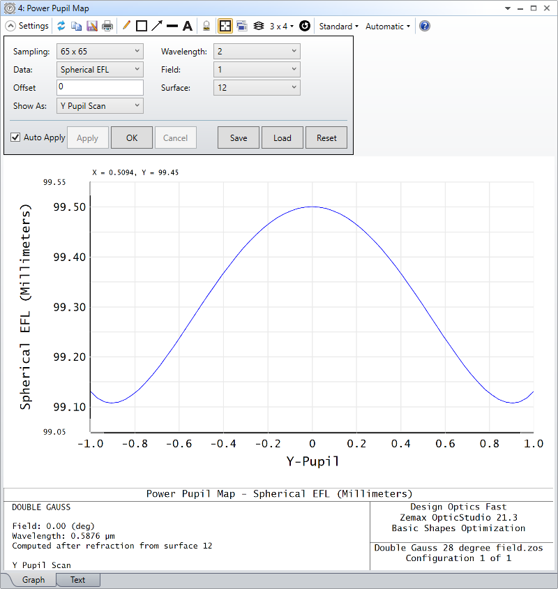
Rather than debate definitions, have a look at Analysis...PAL/Freeform...Pupil Map to see how the focal length of the lens varies with pupil position for a given field:
This example was made with the double Gauss sample file and it shows how on-axis focal length varies across the pupil of the lens. You can see focus and spherical balancing in this example. I would use this plot to see how well a single ‘focal length’ describes your system. There is an associated Power Field plot that shows power/focal length as a function of field for a specified pupil point.
The Help File description of this feature is very good (if I say so myself) 😎
When it comes to defining the magnification of a lens, you can do it on a single ray but this has the same weakness as a focal length in the presence of aberrations. It’s usually better to look at the encircled energy and define say an 80% DENC as the y-position. The y-heights at which you have 80% of image and object encircled energy gives you a physically meaningful magnification.
Last, the text listing of the Relative Illumination data also includes data for the Effective F/#. The Effective F/# is the F/# required for a perfect optical system with 100% transmission and a circular exit pupil to have the same image illumination as the system being evaluated. The Effective F/# is computed by E=SQRT(pi/4A) where A is the area of the projected solid angle of the pupil in cosine space weighted for system transmission. The Effective F/# is a useful metric for comparing the brightness of the image formed by different optical systems, because it accounts for RI and is independent of the aperture shape. For more information, see "F-Number and the radiometry of image forming optical systems with non-circular aperture stops," R. Siew, Proc. of SPIE Vol. 5867 (2005).
Unfortunately, I don’t think your expression for focal length is correct. Both the EFL and EPD are, by definition, paraxial quantities (i.e., they are calculated using paraxial math). Paraxial quantities are the same as first-order quantities (no aberrations). So there is no such thing as a non-paraxial first-order system parameter.
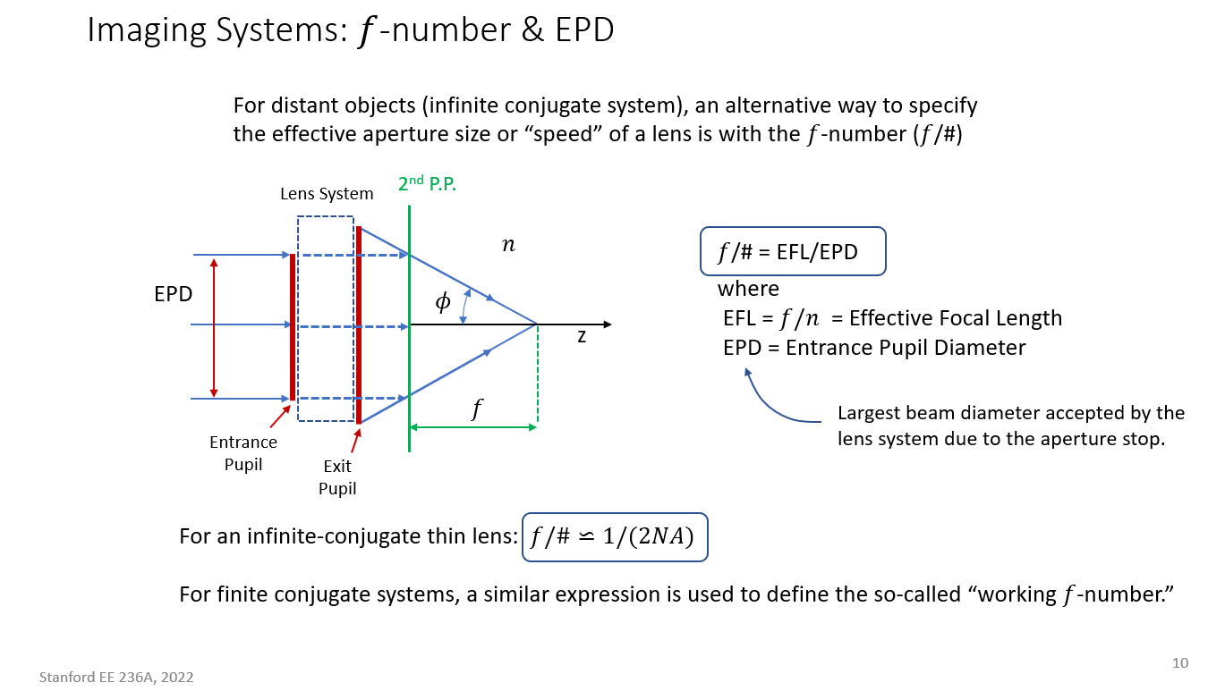
When the image space refractive index is unity, the EFL corresponds to the distance from the back focal plane to the 2nd principal plane, independent of the NA. Here is a viewgraph that I used last quarter when teaching an optics class that may be of some help:
The f/# in the viewgraph, which is based on a standard definition, corresponds to the “Image Space F/#” in OpticStudio. Here the angle phi can be found from the slope of the paraxial marginal ray by taking an arctangent. For an actual objective lens, the angle of the real marginal ray will typically be different than that of the paraxial marginal ray (see “Working F/#” in OpticStudio), but that’s a separate issue, unrelated to the lens focal length.
So, while you can use your formula to calculate a length, it’s not the lens focal length. Off hand, I’m not sure for what purpose you would use this alternative length. The EFL, on the other hand, is useful for relating the incoming angle to the focal spot location (and therefore for calculating distortion, say relative to f-tan(theta), where f is the EFL and theta is the incoming angle).
Hope this helps…
Regards,
Jeff
PS: As a side note, you might find this link helpful for simulating an ideal high-NA objective:
Allow me to clarify some details: When I say ‘non-paraxial focal length’, I mean a focal length that satisfies the relation: NA = sin(atan(0.5*D/f)) as opposed to the approximated relation: NA = 0.5*D/f (which is the paraxial approximation, hence my ‘non-paraxial’ terminology).
For any real system, both the entrance pupil, image-space NA and plane of focus should be well-defined and measurable, thus the focal length should be well (enough) defined.
My goal with finding the so-called ‘non-paraxial focal length’ is to be able to determine the system magnification, which depends on the focal length of the objective. I’m concerned that because the approximated relation NA = 0.5*D/f deviates significantly from the exact relation when the NA is high, I would not yield the desired magnification.
‘Focal lengths’ are slippery things when the system is not well described by paraxial optics, because they are attempts to describe the system by a single ray. The classic Image Space F/# is just the ratio of the paraxial effective focal length calculated at infinite conjugates over the paraxial entrance pupil diameter. Note that infinite conjugates are used to define this quantity even if the lens is not used at infinite conjugates.
Working f/# is defined as 1/(2nsin(theta)) where theta is the real (not paraxial) marginal ray angle, and the marginal ray is traced at the specified conjugates on the lens instead of assuming the object is at infinity.
Rather than debate definitions, have a look at Analysis...PAL/Freeform...Pupil Map to see how the focal length of the lens varies with pupil position for a given field:
This example was made with the double Gauss sample file and it shows how on-axis focal length varies across the pupil of the lens. You can see focus and spherical balancing in this example. I would use this plot to see how well a single ‘focal length’ describes your system. There is an associated Power Field plot that shows power/focal length as a function of field for a specified pupil point.
The Help File description of this feature is very good (if I say so myself) 😎
When it comes to defining the magnification of a lens, you can do it on a single ray but this has the same weakness as a focal length in the presence of aberrations. It’s usually better to look at the encircled energy and define say an 80% DENC as the y-position. The y-heights at which you have 80% of image and object encircled energy gives you a physically meaningful magnification.
Last, the text listing of the Relative Illumination data also includes data for the Effective F/#. The Effective F/# is the F/# required for a perfect optical system with 100% transmission and a circular exit pupil to have the same image illumination as the system being evaluated. The Effective F/# is computed by E=SQRT(pi/4A) where A is the area of the projected solid angle of the pupil in cosine space weighted for system transmission. The Effective F/# is a useful metric for comparing the brightness of the image formed by different optical systems, because it accounts for RI and is independent of the aperture shape. For more information, see "F-Number and the radiometry of image forming optical systems with non-circular aperture stops," R. Siew, Proc. of SPIE Vol. 5867 (2005).
I’ve tried to plug the working F# to the exact relation NA = n*sin(atan(0.5/F#)), and the result I got was almost exactly the same as the paraxial NA, and not in agreement with the NA calculated as the sine of the image-space angle yielded from the ‘real ray trace’ analysis, so my conclusion is that it too is based on paraxial calculations.
I realize that I’ve omitted an important detail - that the final system is infinity corrected, and so the system magnification is the ratio of focal lengths (in object and image space), and that’s the reason I’ve tried to obtain a focal length value with complies with the exact relation, which assumes infinite conjugate.
Anyway, after some experimenting and reading, I came up with the following workflow that seems to satisfy the exact relation:
Define the system aperture as entrance pupil diameter.
Calculate the image-space NA as the sine of image-space angle yielded from the real ray trace analysis.
Calculate the final system magnification as the ratio between the tangent of the object-space angle and the tangent of the image-space angle (rather than ratio of focal lengths).
We use 3 different kinds of cookies. You can choose which cookies you want to accept. We need basic cookies to make this site work, therefore these are the minimum you can select. Learn more about our cookies.