
Hello, 

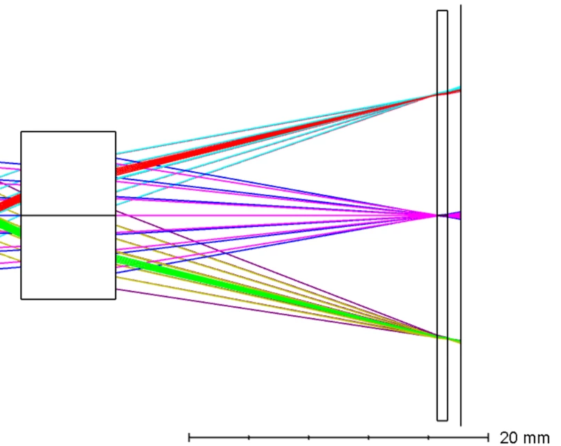
I am trying to simulate a laser triangulation setup and would like to use the “Marginal Ray Height” solve type for the thickness between the last lens surface and the image plane.  
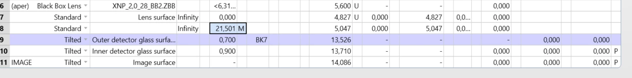
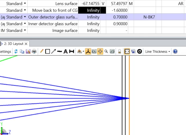
To improve the simulation accuracy, I am adding two surfaces for the detector cover glass between the last lens surface and the image plane. Is there a way to set the “target” of the thickness calculation to the image plane instead of the cover glass?

Or is it only possible by defining the surface thickness as variable and optimizing it? 

Thank you for your help!


Hi Malte,

If you have a fixed distance from the sensor to the front of the cover glass (which is typical), then you can use a dummy surface between the last optical surface and the cover glass (between S8 & S9), set the thickness to -1.6 and then keep your cover glass thickness as 0.7 and your CG to sensor as 0.9.  The LDE & Layout would look like this (the highlighted surface is the new dummy surface at the marginal focus and the front of the CG is -1.6mm in front of the marginal focus):


Works perfectly! Thank you very much Michael! 😊


Reply