Hello together, 


I have a problem using the IMAE operand in a tolerance script. I would like to compute the IMAE for different object sizes in a MC simulation using a tolerance script. The essential part of the merit function is depicted in Pic2_Merit.png whereas the essential output is shown in Pic1_Result.png. The merit function is called for every MC-file.

Very often (but not always), the value of distinct IMAE operands is not adapted during the calculation and takes the value of the preceeding IMAE operand as depicted in yellow in Pic1_Result.png. Is this familiar to anyone? Is it avoidable by e.g. increasing somehow calculation time for the operand? 


Thank you and best regards,


Gregor


I found a way around by inserting every IMAE operand in a new merit function and call/compute it separately. Yet, I wonder if this is a bug or if this can be avoided by adapting the settings. 


Good job debugging it, but this sounds like a bug to me. I’d email support@zemax.com and raise a support ticket.

That said, it’s odd to think of IMAE in a tolerancing application. Are the tolerances really so big that they affect the overall transmission of the lens system significantly?

  • Mark

@Gregor:

I tried a simple test to replicate your problem, but everything seems to look okay.  I used the sample Double Gauss 28-deg. lens model, placed an aperture on the image plane to limit the throughput for a given object field size.  The merit function consists of three IMAE operands with different field sizes.  For tolerancing, the aperture is randomly decentered in the y-direction. 

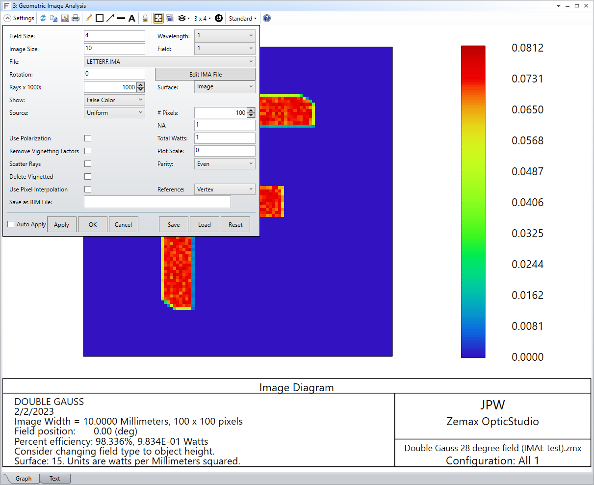
Here are the Geometric Image Analysis settings that were saved before tolerancing:


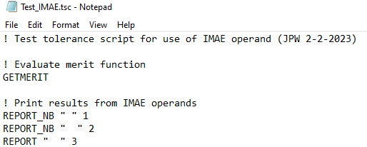
Here’s the tolerance script I used:


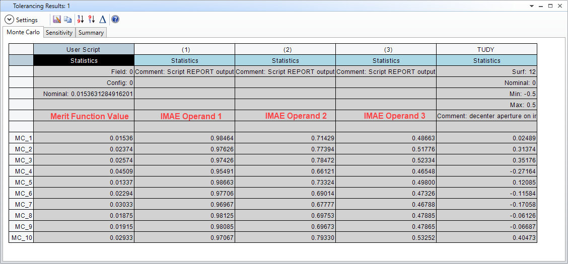
The results of a Monte Carlo run look fine:


It’s hard to know what might be going on in your case without seeing more detail.  It might be some detail associated with your tolerance script.

Regards,

Jeff


Thank you for the fast answers!


@Mark: In fact, IMAE is used in my example to geometrically calculate a coupling efficiency from, lets say, one MMF to another (illumination optics). It is the wish to get a feeling for the change of the coupling efficiency with aberrations. Of course, their might be more mathematical approaches to get this feedback but the communication with the client is much easier with this simulation. 

@Jeff: I took the same file you used. Unfortunetly, I couldn’t imitate the problem here as well. 

Anyways, thank you for the feedback! 


Reply