Dear Zemax Team,

my optical system is a mixed POP and geometric propagation model, i.e. I have checked “Use Rays to Propagate to Next Surface” in the Lens Data Editor Physical Optics dialog for parts of my optical design, where I don’t expect significant diffraction effects, also improving processing time and avoiding phase aliasing effects.

The tolerance analysis adds Dummy surfaces into the design, e.g. for the TEDX operator, which is convenient to see e.g. in the MC_Best.ZMX file.

I have noticed that the setting “Use Rays to Propagate to Next Surface” seems to be not set for the dummy surface as in the original lens data (i.e. it is unchecked, althought the original lens data was checked). In my interpretation this means, that the propagation of the dummy surface will be, if I do a physical optics run, as POP propagation, not ray propagation. As my resolution at this Dummy surface is not properly set (or cannot be achieved), the propagation results will be significantly altered if I press the POP run in MC_Best.ZMX (which will use POP where I don’t have the resolution properly set) compared to my original file.
This is also an issue, if I produce an Overlay Monte-Carlo Graphics (from the Tolerance Dialog) of a POP Cross X irradiance display, which will be also based on the wrong settings of the Dummy surfaces’ Physical Optics setting (i.e. unchecked “Use Rays to Propagate to Next Surface”) .

Can you think of a work around for the tolerance run, so that I get a correct POP Cross X irradiance display. Maybe this is something to be altered in the Zemax code, if I understand the problem correctly?

Many thanks again for your always great support.

Markus

Oh Lordy, that’s true. The dummy surfaces will not have that flag set.

There is a workaround, and it’s actually one of my preferred methods for setting up tolerances in complex systems. Try this:

Use the tilt/dec tool to insert all the coordinate breaks you need, before starting the tolerancing process. Satisfy yourself that everything is tilting and decentering around the correct points. Set the POP flags on all dummy surfaces, and ensure that the results are unchanged when all tilts and decenters are zero.

Then tolerance using TU** operands instead of TE** operands. Use these to program the tilts and decenters of the first CB of each tilt/dec pair.

Another benefit of this approach is that the surface numbers will not be changed by the tolerancer, so the overlay MC feature will work as expected.

  • Mark

Many thanks Mark, I will have a look into this when I find some time. Always gets me more insight into Zemax :)

Markus


Hi Mark,

it looks that changing the tolerancing process to a more manual one with TU** instead of TE** operands seems to be quite an effort. I will see when I will find time.

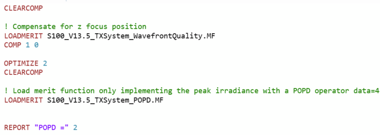
One more thing I noticed. I wrote my own little tolerancing script, first optimizing the SMF fiber distance with a wavefront merit function, and then having a very simple MF with just a POPD operator (data=4) to measure the peak irradiance of my beam at the target distance.


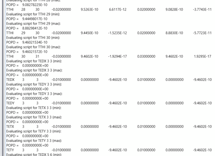
When I run tolerancing again (with the original TE** operator), I get nice POPD peak irradiance value, until the first time an operator is loaded (TEDX) to introduce a dummy surface into the lens data (and changes the length of the Lens Data). Then POPD returns zero.

I guess, the reason for this is, that the configuration I saved in the POP GUI with my POP settings is not valid anymore for the longer lens editor file, especially the setting End Surface (it is not pointing to the image surface anymore). When I look into the MC_WORST.ZMX file, I can see this when I load the POP settings into the GUI. The End Surface then points to a surface with “Use Rays to Propagate to Next Surface” in the Physics Optics settings of the Lens Data editor. This throws an error message:

When I correct the POP settings, the POPD works again. So I assume, it also returns zero in the tolerance run due to this error.

I guess the work-around would be again to build your own tolerancing file with TU** operators? :)

Thanks again

Markus


I think you have identified the problem correctly. As Mark mentioned and you’ve found, the TU* operators allows direct control over the placing of Coordinate Breaks and thus avoid the problem with the dummy surfaces. If you would like us to take a look at your exact system, please feel free to open up a case, but I think you’ve got it.


Reply