Hello, I’m trying to learn how the merit function definitions work. I went through a tutorial on it (https://support.zemax.com/hc/en-us/articles/1500005490261) and thought I understood how it worked, but when I try to implement something similar to what they used in the tutorial, the merit function does not compute the value and it is unable to optimize.

Additionally for the merit function types I don’t know what the codes mean exactly. is there some place to find this information? I tried the help (?) with no success.
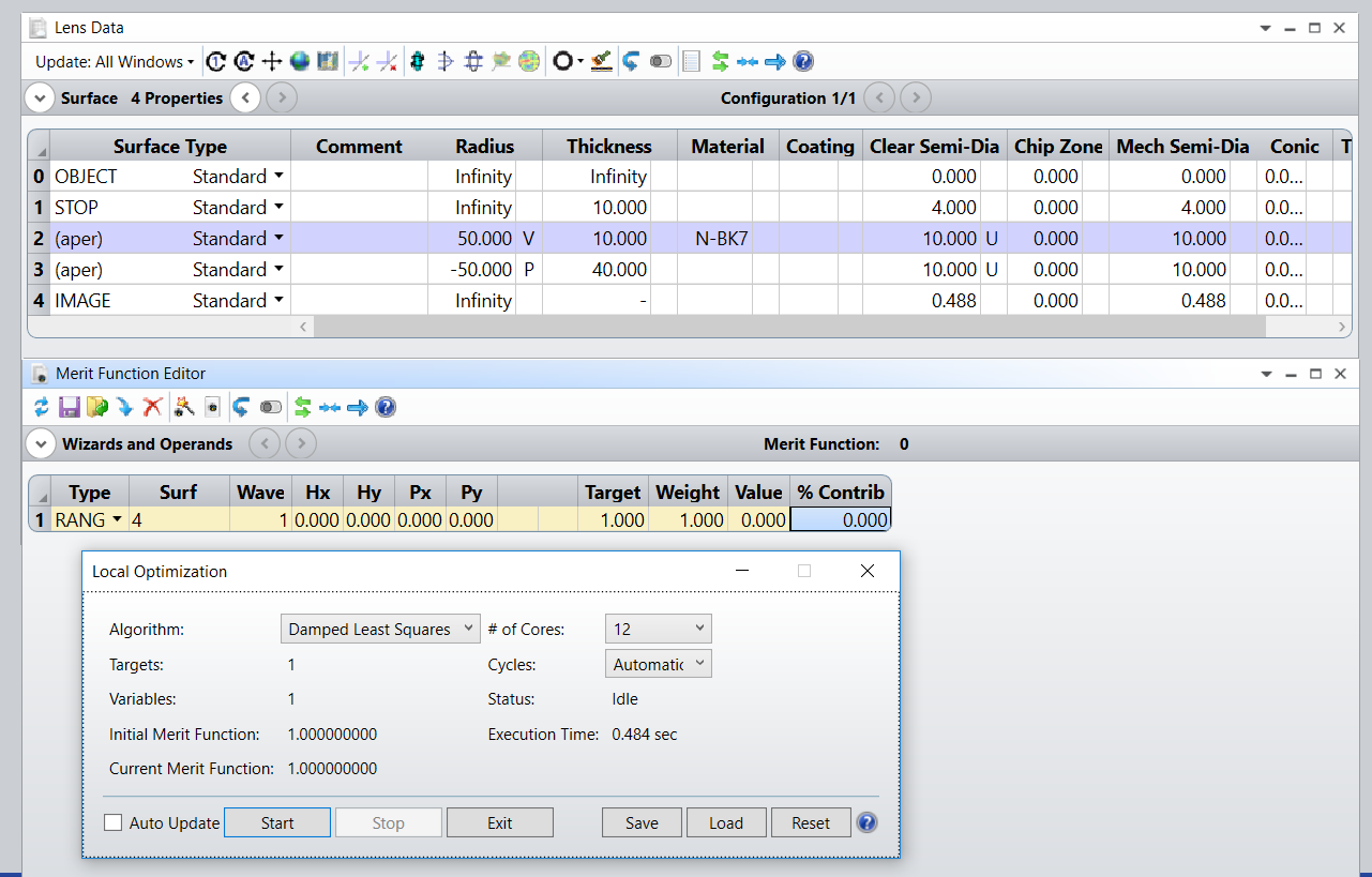
 

Hi Sebastian,


With your RANG operand, you are asking that the chief ray makes an angle with the optical axis. Your variable is the curvature of your lens. The problem is that your chief ray is colinear with the optical axis, therefore it always hits perpendicular to the vertex of your lens no matter the curvature, and by Snell’s law, continues its trajectory unchanged. Try changing the value of the Radius manually, and notice the angle the chief ray makes with the optical axis (the two remain colinear).

If you prompt the Help File with F1, and go to the Search tab, you can type Merit Function Operand, and you should be able to browse all the operands. I’ll check where it is exactly in the Help File when I get on my OpticStudio laptop, but I believe it is not too difficult to find.

Let me know if this makes sense, and perhaps you could explain what you are trying to achieve so people can offer further guidance.

Take care,


David


Okay, it calculates the angle only for the centre ray. That make sense.

Via the F1 Help search you described, I was able to find a list of the Operands.


I initially thought that RANG was measuring the beam divergence which is why I wanted to use it. My intention is to build a system as follows:

  • diverging gaussian laser beam
  • collimating lens
  • tuning lens A
  • tuning lens B
  • measure divergence of the outgoing beam here.

I would like to tweak the separation distance between tuning lens A and tuning lens B to adjust/study the divergence of the outgoing beam after B.


Thanks for helping.


Hi Sebastian,


Allow me to clarify. RANG doesn’t only calculates the angle for the chief (“centre”) ray, it can do so for any ray. The reason it calculated the angle for the chief ray, in your example, is because you set it up that way. If you look the headers of the columns of the Merit Function editor, you can see Hx, Hy, Px, and Py. Those are called Normalized Field, and Pupil Coordinates, respectively. You can find out more about those in the Help File under:

  • Conventions and Definitions > Normalized Field Coordinates
  • Conventions and Definitions > Normalized Pupil Coordinates

By specifying those for values, you define a single ray in your system, and by leaving them all to zero, as you did, it is defining the chief ray. If you look closely in the knowledgebase article, they used RANG with Hx = Hy = Px = 0, and Py = 1. By doing so, RANG measures the angle of a marginal ray (in the Y-Z plane), and for a perfect Gaussian beam, this can be used as a measure of divergence. I would recommend getting more familiar with the normalized coordinates as they are used in many other operands. In fact, most operands use a single ray to compute their return values and the ray of interest if chosen with Hx, Hy, Px, and Py.

You could also use the afocal spot diagram, and related operands to measure the divergence as explained in the knowledgebase article, but it might be best to start with RANG.

Let me know how you are getting on.

Take care,


David


Hello David,


Thanks for all the help.

By setting Py to 1 as you said, I am able to optimize for and adjust outgoing divergence, however the optimized solution Zemax gives, is not a collimated beam as it should be. I suspect this might be due my beam being (intentionally) clipped by a few apertures along the way. If I reduce Py to 0.1 (or lower), the optimal lens separation distance makes sense, but the beam divergence seems to be significantly smaller than expected. I don’t know if Optics studio is accounting diffraction properly.


Hi Sebastian,


The RANG operand ignores apertures. Even if the ray looks clipped on your layout, for the purpose of RANG, it is still traced through all the surfaces, and generates an error if a surface is missed.

Diffraction in OpticStudio is a sensitive topic. It might not be accounted for in the way you’d expect it to. During raytracing, diffraction is absent. Some analysis make use of the raytraces to compute metrics such as the Huygens integral, which would give you the Huygens PSF/MTF, but they would only account for the diffraction after the exit pupil. If you need a more comprehensive account of diffraction, you might need to use tools such as Physical Optics Propagation or POP, and even then, you should be careful of its limitations. Fast beam, those with a relatively high divergence, are not well supported. I leave you to browse the knowledgebase articles to learn more about POP, but a good starting point is probably this one.

Can you share a *.ZAR archive of your design? The best way to do it is by pressing File..Create Archive, and then put this file into a *.ZIP that you upload on this thread.

Take care,


David


Hello David,


I have attached the zemax file. My goal is to study the measure the divergence of the beam at the test plane (14) by adjusting the separation of the lens and the mirror (thickness of 8 which is dictates thickness 11). One way of measuring this divergence was to also measure the spot size on the focal plane (18), as I was/am having issues measuring it other ways.


Reply