
I am comparing the linked materials attached below.
I think the biggest setting difference between the two materials is Object Surface Thickness. So I am comparing the following two cases.
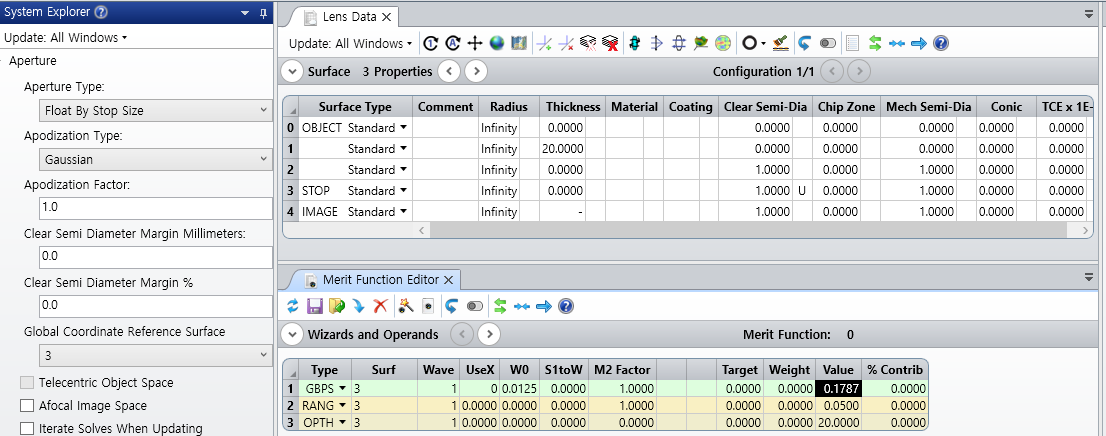
Case 1
- Surf #0 Thickness = 0
- Surf #1 Thickness = 20
- …
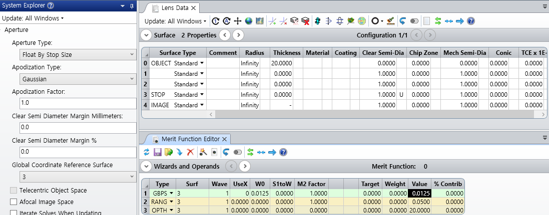
Case 2
- Surf #0 Thickness = 20
- Surf #1 Thickness = 0
- …
Analysis Type
- Operands
- RANG
- GBPS
- OPTH
- Tool
- Analyze...Gaussian Beam...Paraxial Gaussian Beam
- Stands Spot Diagram
As a result,
RANG, OPTH, and Standard Spot Diagrams have the same values for Cases 1 and 2.
However, the result values for GBPS and Paraxial Gaussian Beam are different.
So I wonder in which case to set Surf #0 Thickness = 0.. in which case to use Surf #0 Thickness <> 0. And I'm curious about the physical difference between the two cases.
Note that, I know that GBPS outputs beam size based on paraxial rays.
