ISO Element Drawing: open issues


Userlevel 2

I'd like to point out some mandatory features which, in my humble opinion, the ISO Element drawing utility lacks. I'm probably referring to all well known issues, but still, I believe them to be of paramount relevance to be left unsolved over the years.


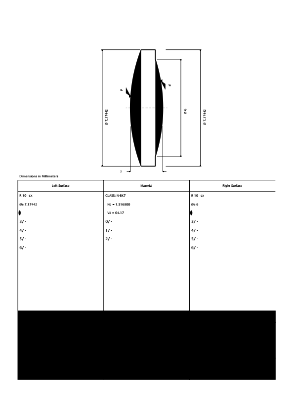
1) support for triplets.


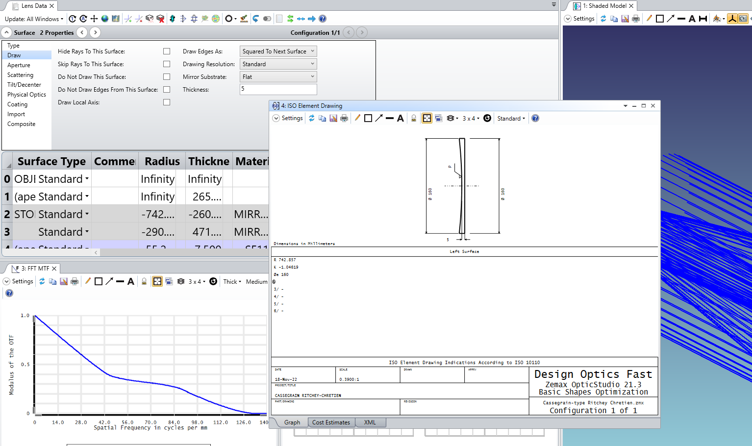
2) xml file support for doublets/triplets. More on this, I report a sneaky behaviour of the current feature: if a doublet design is saved, no error is reported by OpticStudio and an empty xml file is saved instead, so that the average user can believe its manually inserted data are securely saved, but actually they are not. When opened, such xml file just reports the string 'XML output is not currently supported for doublets'.


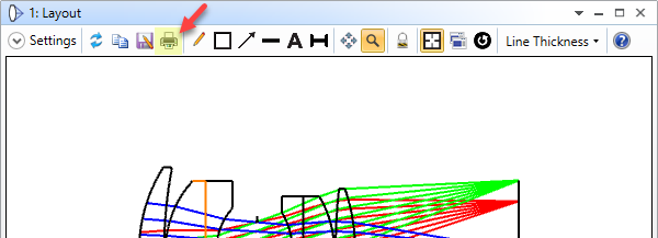
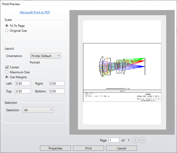
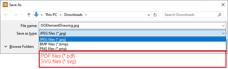
3) drawings saving in a native vector format, such as pdf or svg. At the present time an external pdf printer sw is needed to do so, often with unpredictable results. The same request holds for every graphic output of OpticStudio (diagrams, histograms, plots,...). The chance to have a vectorial output would be great for preparing presentations and scientific documentation, with the inherent possibility of altering the graphic output based on one's typhographical needs, without having to replot/reformat every time by trial and error in OpticStudio.


15 replies

Userlevel 5
Badge +1

Hi Alberto,


Thanks for posting in the forums here and sharing your feedback! I've gone ahead and made feature requests for your first two items. I should note that feature requests are not a guarantee that they will be added to a future release -- rather, they are weighed based on impact to the userbase, difficulty to implement, and the number of users who request it. Still, we appreciate all feedback on OpticStudio's functionality, as it helps guide the future of the software, so thanks for your input.


Regarding point 3, just some additional questions to get some more context: when you currently export graphics, do you use the 'print' button on the toolbar of any given analysis window?


While this might not be exactly what you're aiming for, it does allow you to use Window's default 'Print to PDF', though it will put the image onto an entire page:


If this isn't what you're looking for, then are you hoping for a functionality more in-line with something like an additional toolbar button for graphics export to PDF/vector format? Something else in mind? This is just to help ensure I'm getting the core motivation for your request correct before I submit it internally.


Thanks again for your feedback here!


~ Angel

Userlevel 7
Badge +3

Hey Angel, there appears to be a bug in the 20.3 release with respect to graphic export in the ISO plot. It does not use the 'Custom' resolution setting


It only exports at Window resolution and not at the specified resolution, which is why the ISO export is looking so grainy and pixelated.


- Mark


Userlevel 7
Badge +3

Also Alberto, most analysis windows except the layouts do support export to SVG. I don't think the ISO does, as it is a member of the layout family. But spots, ray fans etc all support SVG export.

Userlevel 3
Badge

I noticed the OPD fan window does not export graphics the same as other analysis windows. 

Userlevel 3
Badge +2

Hi Sean,


The OPD fan allows to save the image as .JPG, .BMP and .PNG. Is not the same for you? 

Userlevel 3
Badge

Hi Berta,


Yes, those options are available. I guess the difference is no SVG option for the OPD window. Also when saving the OPD plot there are no options for resolution available like in other windows. 

Userlevel 2

Hi Angel,


thank you for your support. What I have in mind is something as simple as this:


Thank you Mark for pointing out the .svg export functionality. I'd like the same to be applied to the ISO Element Drawing and to the Layout.


Regarding the 'Windows Print to PDF' functionality, I believe it can't be taken as a robust PDF export modality, as it relies on the operating system configuration and frequently ends up in unexpected behaviours. As an example, I used it with no issue on my previous machine, but I cannot use it now on my current machine because it messes up with area fills. 


Of course I could make it anyway with a different (to be installed) PDF printer, but a 'Save as PDF' functionality would be better to me with no doubt.

Userlevel 5
Badge +1

Hi everyone,


Thanks for your posts here! After some investigation, I found a previously-logged bug report on the Classic layouts for various windows having issues with the Print to PDF functionality, resulting in the same black boxes Alberto has shared. I suspect that the ISO Drawing tool is using the same graphical settings as the Classic windows, hence the error there. This also seems to be the case for the Ray Fan/OPD plots, as there is no 'Classic' tab option available at the bottom of the window (when you have 'Enable Classic View' selected in your Project Preferences'):


I have just updated the bug report with this information, and I will also submit a feature request to bring the OPD/Ray Fan plots under the new graphics representation, which I think would result in the same exporting behavior as other windows. I should note that feature requests are not a guarantee that they will be implemented in a future release, as they are weighed on difficulty to implement, impact to our userbase, and the number of users who request it. Still, we appreciate all feedback as it helps guide the future of the software!


Please let us know if there any more questions here. Thanks!


~ Angel

Userlevel 2

Dear Zemax Team,

is there a way to increase the plot resolution, when saving an ISO plot to jpg or copying it to the clipboard? E.g. Tolerance numbers come out pretty unreadable.

Thanks for the support.

Markus

Userlevel 7
Badge +3

The ISO diagram is one of the most important methods of getting design information out into the real world. I’d really like to see it get an overhaul with all the features discussed here.

Userlevel 1

Out of interest is there a way to define the shape of an optic in the ISO output - for instance if I have a rectangular aperture for say a cylindrical lens or square mirror, this is not shown in the output drawing. 

Userlevel 5
Badge +2

Hi All,

Thanks for your comments here on the forums.

Markus, regarding the resolution, the issue is that the ISO Element Drawing is using our old classic charts (not our latest graphic libraries). This is why the new Improved Graphic Export is not implemented on that analysis. There is an open feature request in our internal system to update the ISO Element Drawing to the newest library, and I have gone ahead and added your vote this feature request. 

Please keep in mind that feature requests are weighed based on impact, difficulty to implement, and the number of users who request it. A request is not a guarantee that the feature will be added to a future release. These feature requests are very important to us and shape the future of OpticStudio, so we appreciate your input regarding desired functionality.

As a workaround for now, you can try to print as a pdf to have better resolution.

Matthew, unfortunately what you would like to do is not possible, as the ISO element drawing is a standard that can only be used with circular apertures and rotationally symmetric lenses.

As a workaround I would suggest to export the lens to STEP by clinking on File > CAD Files, and then using a CAD software to generate the drawings of the lens. If you do so the rectangular aperture of the lens should be shown in the drawing automatically.

If you have any further questions, please let us know and we will be happy to help!
Best,
Csilla

Userlevel 1

I’d like to see more functionality for creating drawings for mirrors.  Currently there’s only the surface option.  The work around I used was to create dummy substrate behind the mirror.  But then I can’t auto add the tolerancing data.  It’s a bit of a manual process.  If there was just an option to add material and an auto “ground surface” that would be very helpful

Userlevel 7
Badge +3

Hi Alex,

Good news! That is already supported!

In the Lens Data Editor, click on your mirror surface, and in the Properties go to the Draw tab. Select ‘Mirror Substrate’ to be curved or flat, and give it a thickness. This is then used in all drawings, including the ISO Element Drawing

Userlevel 1

Hi Mark,

Yeah I saw that.  However, there doesn’t seem to be a good way to put requirements on the substrate other than adding a note.  I also don’t see how I can add a tolerance to the thickness of the substrate.  Sometimes it shows up, other times it doesn’t.  

Reply