Image-space Telecentric lens in a THz imaging system

  • 31 January 2022
  • 7 replies
  • 568 views

Hello,

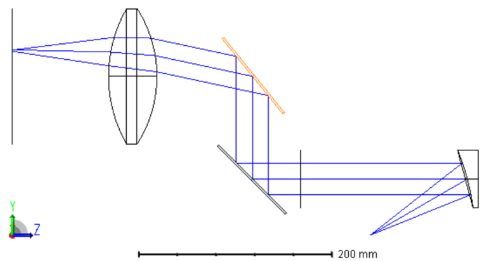
I am trying to implement a THz imaging system. My feed is a THz gaussian source (typically in the range of 500 GHz), which is collimated using an Off-Axis Parabolic (OAP) reflector. Then, in order to have scanning of the imaging system in XY plane, I have two scanning mirrors which rotate in X and Y planes. (A better visualization is in the figure below).

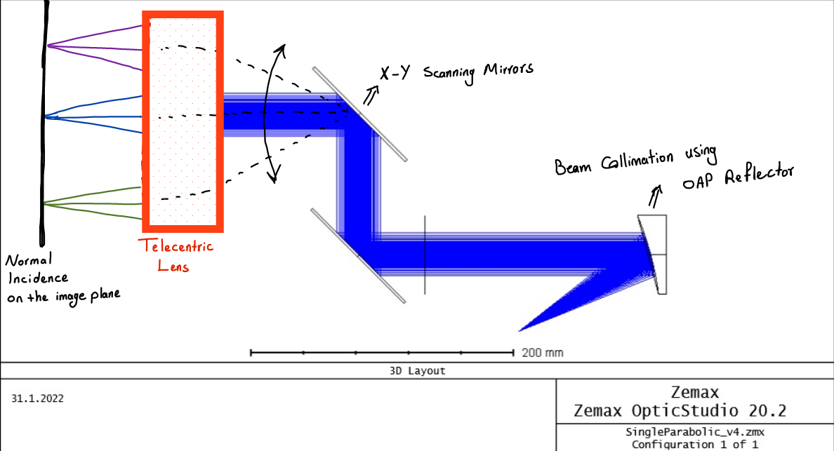
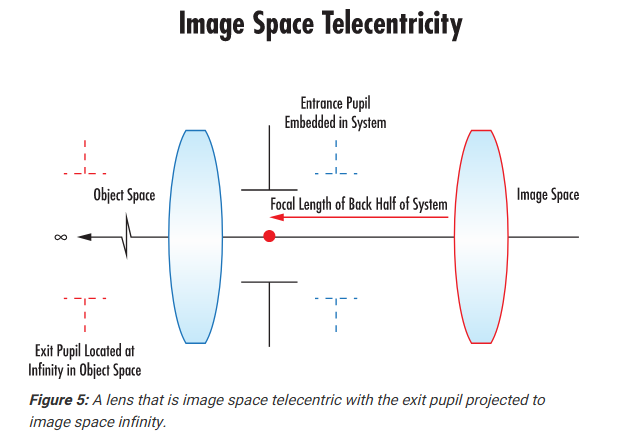
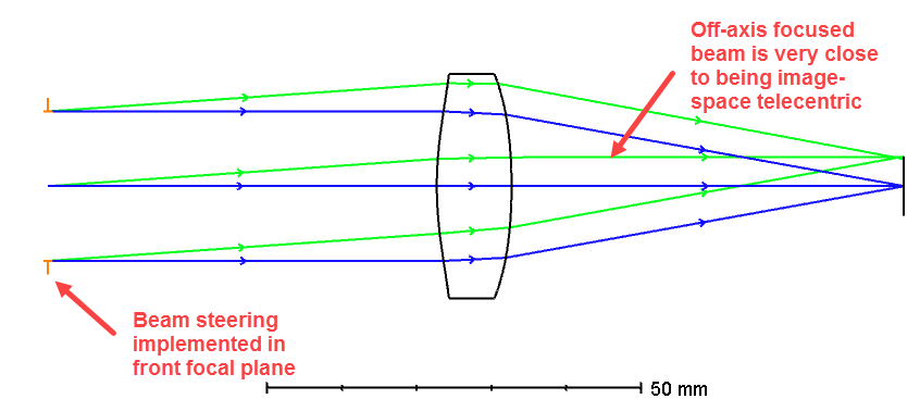
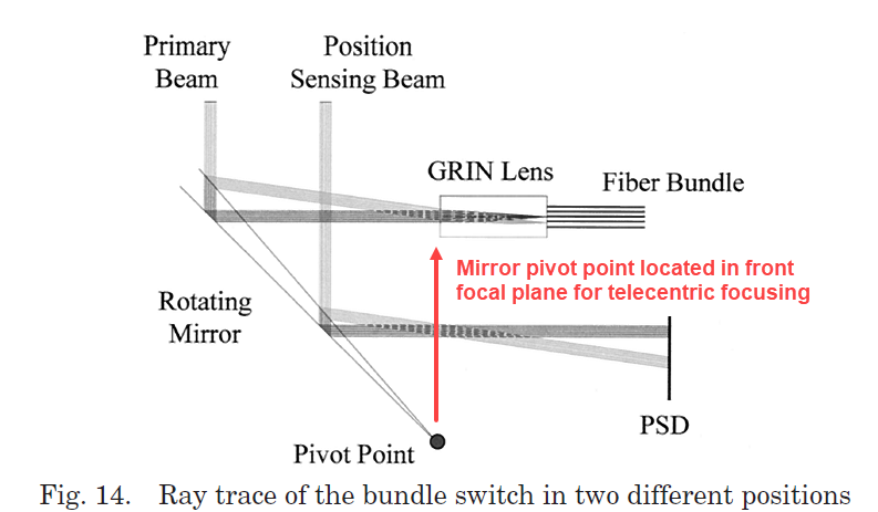
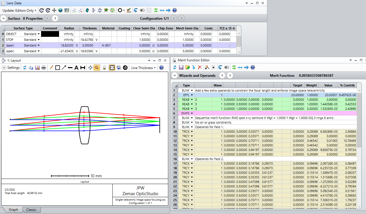
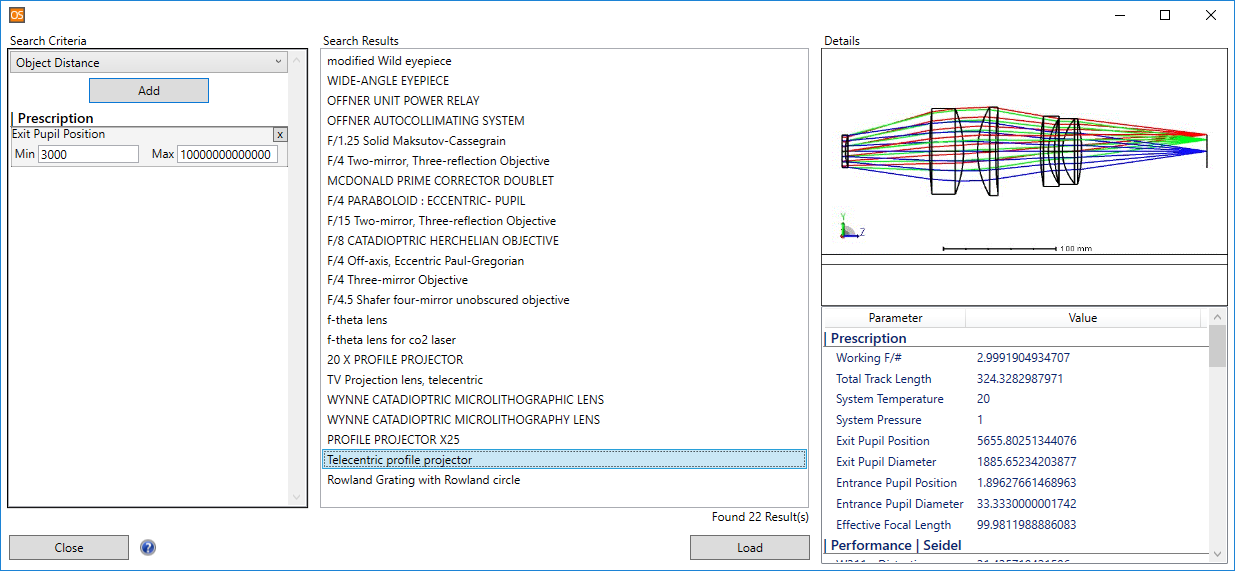
At the final stage of the imaging system, in order to focus the collimated beam and also have a normal incidence on the image plane, I need to use a lens that is telecentric in the image space.

Could you please help me on how to use such a telecentric lens? Since I am planning to implement this setup experimentally, as well, I need it to consist of as few seperate lenses as possible.

If you could send me a zemax file to use such a telecentric lens on a THz collimated beam, or if you could modify the zmx file that I have attached to this post, I would really appreciate it!

Thank you very much for your time, in advance!


Sincerely,

Pouyan Rezapoor


7 replies

Userlevel 7
Badge +3

I haven’t opened your model, but from the system sketch you provided it appears that if you simply place a *single* dual-axis tip/tilt scanning mirror in the front focal plane of your last lens, the beam will be telecentric in your image space focal plane.  Is your plan to use a dual-axis mirror for beam steering, or is the other flat mirror in your setup also supposed to steer the beam?

Actually each of those mirrors are responsible for steering the beam in one direction. For example, one of the mirrors is tilted only in the x direction, and the second mirror is only tilted in the y direction. It could be understood easier if we only assumed one mirror, and have a linear scanning of the beam only in y direction.

The problem is that if one of the mirrors is tilted, then the incidence angle to the image plane will not be normal.

In order to have a normal incidence angle to the image plane while scanning the mirrors and also focus the collimated beam on the image plane, the best approach is to use a telecentric lens, in the place that I have shown in the figure above.

Userlevel 7
Badge +3

A lens that is image-space telecentric has an exit pupil at infinity, which in turn means the aperture stop is located in the front focal plane  -- that’s the underlying basic principle.  The Edmund Optics website has a nice discussion here Telecentric Design Topics :


For a beam-steering and telecentric-focusing application, this means the steering function should be implemented in the front focal plane.  Here is a very simple example using the even asphere sample lens:


If the steering is done in a different plane, then the image space is no longer telecentric:


I’ve used this principle to construct a fiber-optic switch (ref: Fiber Bundle Switch (see Sec. 4) ):


If a single dual-axis mirror cannot be placed in the front focal plane, then two orthogonal mirrors can be placed in different locations, but they should both have their pivot points located in the focal plane.  Here is an example from the fiber switch:


Hope this helps…

Jeff


Thanks a lot for the comments.

I will try to recheck the beam steering in the XY directions, but my main problem is in the design of the telecentric lens.

For now, we can imagine that we only steer the beam in one direction, i.e., we can assume the first mirror in the figure of the setup above is fixed, and only the second mirror is steered. In the zemax file that I have attached, the beam steering is done by changing the tilt X value in the material properties of surface 12. (We can also use your suggestion and have a dual-axis mirror as the second mirror (surface 12), and we can change the tilt X and tilt Y values in the material properties of surface 12)

My question is more basic. If we have this kind of beam steering, how can we design a telecentric lens? Are there example zemax files on using a lens to be telecentric in the image space? For example, is there a way to design the lens in the figure below to be image-space telecentric?


Userlevel 7
Badge +3

To design a simple singlet lens that is telecentric in image space should be relatively straightforward.  You can place the stop in the approximate front focal plane, use the Merit Function wizard to construct a default merit function (say RMS spot size), then add a few operands to constrain the effective focal length and enforce telecentricity.  Here is a very simple example using three field angles:


But a singlet lens with spherical surfaces will definitely have aberrations that might limit performance in your application (not sure what your requirements are).  For example, for larger field angles, field curvature may become a problem.  In that case a more complicated design with a field flattener can be tried (e.g., as described by Bentley and Olson, SPIE Field Guide to Lens Design, p. 19):


I’ve never designed optics for a terahertz application, so I have no idea what sort of material and/or fabrication constraints exist.  However,  I would think that standard visible lens design concepts can still be utilized, assuming the resulting components are feasible for fabrication.

Userlevel 7
Badge +3

By the way, there are several telecentric lens design examples provided in Libraries → Design Templates, that can be found by searching for lenses with a very long exit pupil location:

They can be used as starting points for modified versions.

Also, you may want to see Ch. 23 (Telecentric Systems) in the following book:  Lens Design 4th Ed. by Milton Laikin.  Some of the design discussed there are already provide in the Design Templates library.


Hi @Jeff.Wilde

Could you please help me designing it for my use case or point me to a good starting point.

I am looking to design a retroreflection system, which is lot like the above question proposed.

The difference being that 

  1. Source/receiver being a single mode fibre @780nm (MFD: 5.3um)
  2. System is a double pass system with the image plane in above question replaced by a mirror and beam couples back to the source fibre.
  3. Instead of scanning mirror, I am using a transmission grating which is tuneable. And deflection half angle is max 1 degree. (The angle seems to be small but the precision of retroreflection required to couple back makes it tricky for me.) 
  4. The beam diameter at grating is about 200um.

 Regards,

Saurabh 

Reply