I would like to use the Tolerancing feature to get a sensitivity analysis for a mirror's position/rotation. Using TE-DX/DY/TX/TY/TZ I got results for the RMS Spot Radius that I could replicate with the RMS vs. Field Analysis. For TTHI I tried two approaches:
1) I placed a coordinate break before the mirror (n) and one after the mirror. The trailing coordinate break has a return solve to n. In the TDE I created an operand as follows: TTHI (n-1) (n-1) 0.00 -0.02 0.02
2) I applied the TTHI directly to the mirror.
Both approaches resulted in different RMS Spot Radii that I could not replicate with the RMS vs. Field Analysis.
How do I use TTHI to tolerance the mirror's z-coordinate?
Best answer by Mark.Nicholson
Hi Jan,
TTHI is a little complicated because it includes its own compensator that controls how thickness tolerances accumulate. See the docs for full details. The best thing to do to replicate TTHI is to go to the Tolerance Data Editor, and right after the TTHI operand you're interested in, put a SAVE operand. Then run the sensitivity analysis, and OS will save the file it creates when it hits this operand. Then you can see exactly what TTHI does. If you change the compensator surface control on the TTHI operand and run again, you'll see exactly how the operand is interpreted.
You can save Monte Carlo files as well so you can see how all tolerances work at the same time. I strongly recommend doing this as it gives you confidence in what the tolerancer is doing.
Thank you for this response. From following your advice, my understanding is:
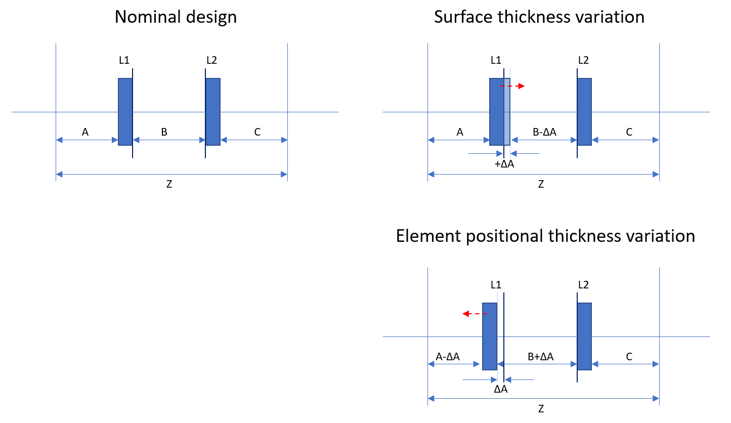
If the lens surface on left grows or if the element is shifted in position to the right of nominal, the adjustment surface decreases to maintain relative positions between L1 and L2
If the lens surface on left decreases in thickness or if the element is shifted in position to the left of nominal, the adjustment surface also grows to compensate the difference and maintain the positions between L1 and L2.
If the lens surface on left grows and the position of the element itself is shifted to the left of nominal. Then the adjustment surface would account for the combined Δ in position.
I still do not understand how we can specify to keep optical surface-to-surface thicknesses at nominal values but apply perturbation only to the element positions relative to its before/after elements in zemax tolerance, i.e., no growth on surface thicknesses but change the relative distance between the optical elements.
I would appreciate it if you had any advice for this.
I still do not understand how we can specify to keep optical surface-to-surface thicknesses at nominal values but apply perturbation only to the element positions relative to its before/after elements in zemax tolerance, i.e., no growth on surface thicknesses but change the relative distance between the optical elements.
I think you have the basic idea. Clearly there must be a change in surface thickness to change the relative distances between components. OpticStudio does not require you to define mounting surfaces, as surfaces just ‘float in the air’ as it were. When you tolerance, you need to define what are the fixed surfaces (typically those you use as mounting references) and what can move relative to them. How thickness tolerances accumulate, and what surfaces are fixed and which move as a result of the thickness accumulation, is one of the hard parts in making a good tolerance simulation.