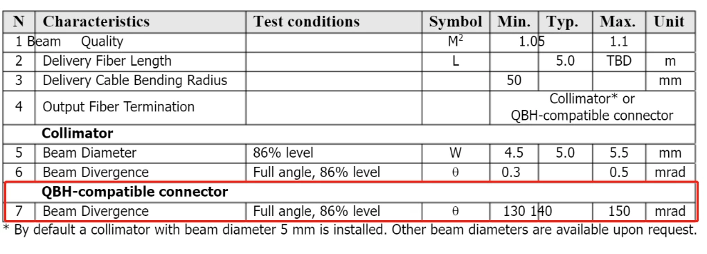
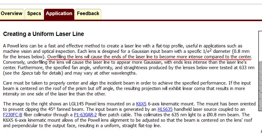
I want to use the non-sequential mode simulation to shape the circular spot output from a single-mode fiber laser into a linear spot. I import the following device parameters to simulate: 1. Single-mode fiber laser 300W, fiber core diameter 20um, M2 1.05, beam divergence 140 mrad. 2. Powell Prism CAD. But the results were poor, with strong energy at both ends of the linear spot. May I ask, is my laser light source setting wrong or Powell prism selection wrong?
Thanks very much!
Best answer by Jeff.Wilde
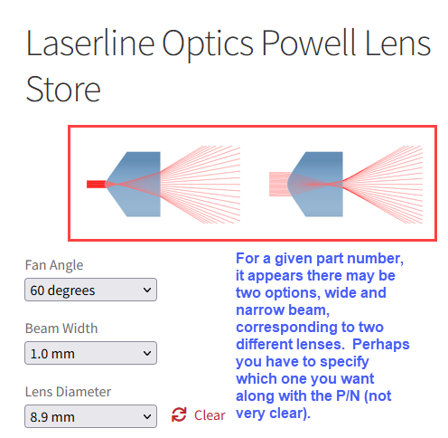
I think the details here are important. A quick look at the Laserline Optics website shows that they offer different Powell lens design options for each fan angle to accommodate a range of beam diameters. However, they also have “narrow” and “wide” beam options (with different CAD models for each) and it’s not clear which one you get for given beam diameter (or if you have to specify this detail in addition to your beam diameter):
In any event, if you are using the correct CAD model (with the right glass, S-TIH6) for your target Gaussian beam width, then you should be getting reasonably reliable results. Not sure what your wavelength is (1.08 um?), but I would suggest you contact the company and make sure you are using the proper CAD model for your particular problem. Also, as Sean mentioned, you want to confirm the CAD model has sufficient resolution for ray tracing (I think it’s probably okay, but that’s another question for the company).
Lastly, I see you are tracing only 5,000 rays, while using a detector with 2000 x 2000 pixels. I would suggest you use significantly more rays, like 1e06, and reduce the resolution of your detector (to say 500 x 500 or less) so that pixels that are being illuminated will receive enough rays to provide a decent SNR.
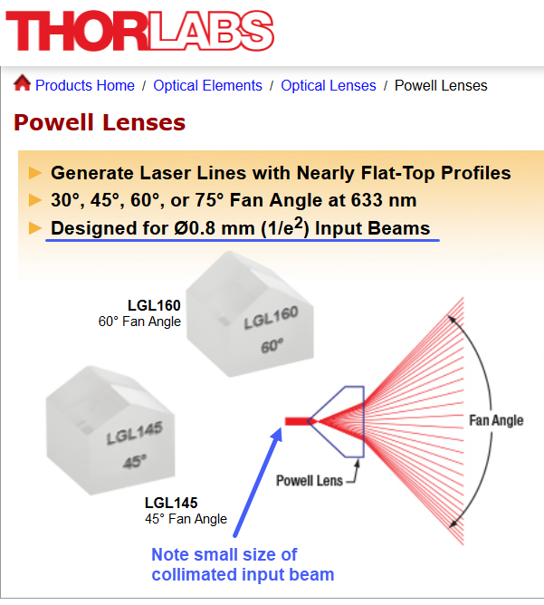
Thank you for your reply,I can't use Thorlabs' Powell lens because their input beam diameter is too small and may be damaged when I use them for high power laser applications. I tried to reduce the diameter of the input beam to about 1mm . Although the energy at both ends of the line spot is decrease, the uniformity of the center energy is worse.
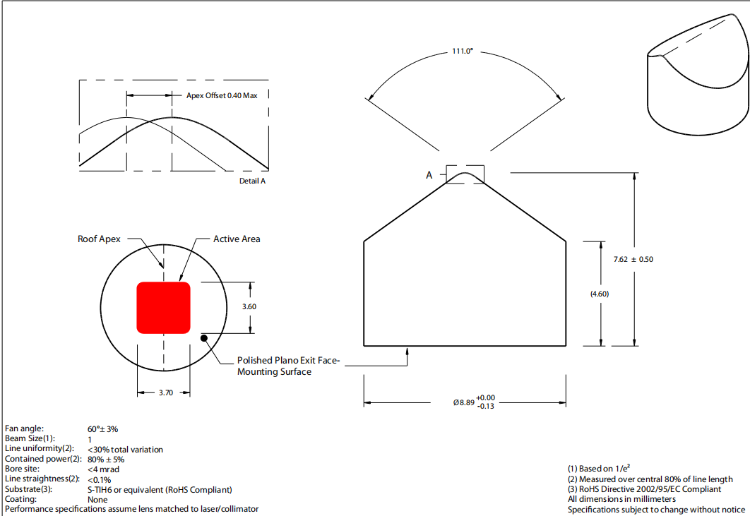
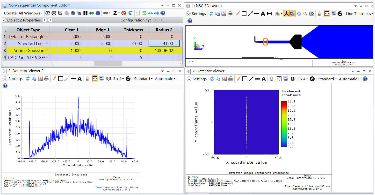
But if i just change the source from a source Gaussian to a source point, and the energy distribution of the line spot looks ok. Does it mean that the Powell lens I chose is not suitable for Gaussian laser applications? Powell Prism address of my choice:https://laserlineoptics.com/powell_primer.html
Do you know if the CAD file for the Powell lens is an accurate representation? Or is it maybe just an approximation without the actual aspheric surface curvature? From my experience, sometimes aspheric lenses when created in CAD software just use splines to approximate the curved surface. I would check with the powell lens supplier.
What lens are you using to collimate the gaussian source? The drawing you shared shows an input beam size of 1mm, but your system layout seems like the beam is larger than 1mm. As stated above, these lenses are designed for a specific beam diameter, and anything larger will have excess power shown at the edge of the line.
I think the details here are important. A quick look at the Laserline Optics website shows that they offer different Powell lens design options for each fan angle to accommodate a range of beam diameters. However, they also have “narrow” and “wide” beam options (with different CAD models for each) and it’s not clear which one you get for given beam diameter (or if you have to specify this detail in addition to your beam diameter):
In any event, if you are using the correct CAD model (with the right glass, S-TIH6) for your target Gaussian beam width, then you should be getting reasonably reliable results. Not sure what your wavelength is (1.08 um?), but I would suggest you contact the company and make sure you are using the proper CAD model for your particular problem. Also, as Sean mentioned, you want to confirm the CAD model has sufficient resolution for ray tracing (I think it’s probably okay, but that’s another question for the company).
Lastly, I see you are tracing only 5,000 rays, while using a detector with 2000 x 2000 pixels. I would suggest you use significantly more rays, like 1e06, and reduce the resolution of your detector (to say 500 x 500 or less) so that pixels that are being illuminated will receive enough rays to provide a decent SNR.
Thanks for your suggestions, I also think there is something wrong with the CAD model I am using, I will contact the manufacturer to get accurate Powell prism data. Later I have new progress I will share the results.