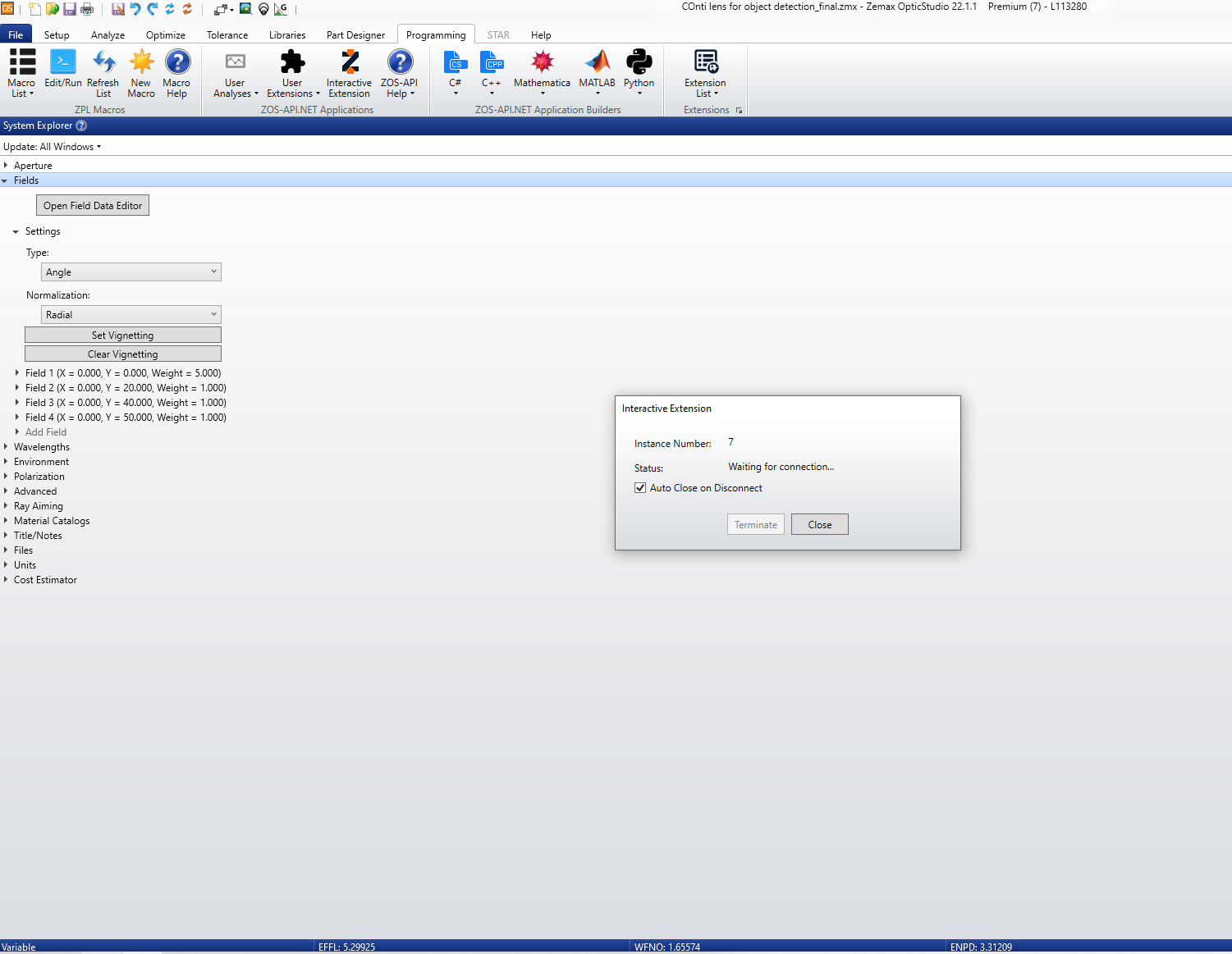
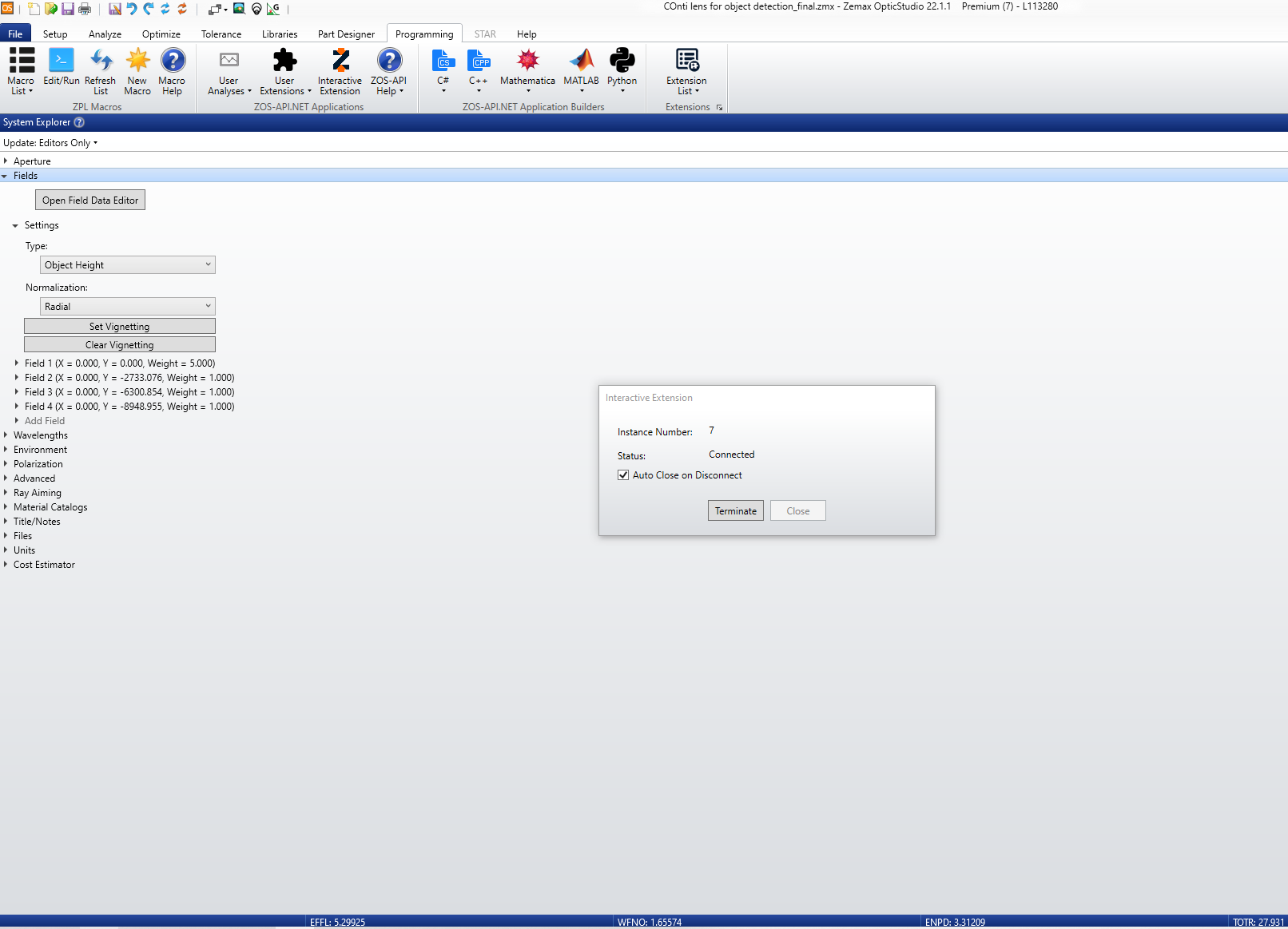
I am using python with the interactive session to run image simulations by varying lens position (to induce defocus and tilt). I have noticed that when the object distance is set to infinity, and when the API connects to the interactive session the field type remains as angles (my default setting). However, when the object distance is set to finite values the field type automatically changes to object height on connection and before the image simulation can run.
Is this a fail safe to prevent errors during image simulation? What would be the significance of such a setting?
Should I change all my image simulations (with finite object distance) to be done with object height type field setting?
Thanks for your answers in advance,
Amit
Best answer by David.Nguyen
Hi Amit,
I think the issue is that you are running a Design Lockdown. Please read this excerpt from the Help File about the Design Lockdown tool:
A number of steps are generally required to take a system designed in sequential mode into a production system. In particular all idealized inputs of the system must be converted into real manufacturing inputs. The Design Lockdown Tool automates this conversion by:
...
Switching from the use of image-based field point definitions (if they are being used) to object-based definitions. The primary wavelength is used for this conversion.
For finite conjugate systems, Object Height is used as the field definition.
For infinite conjugates, Angle is used as the field definition, unless the system is already using Theodolite Angles.
Systems with multiple configurations will not be converted to object-based field definitions; any analysis features or conversion to non-sequential should be manually verified if the sequential system is defined with image-based field definitions.
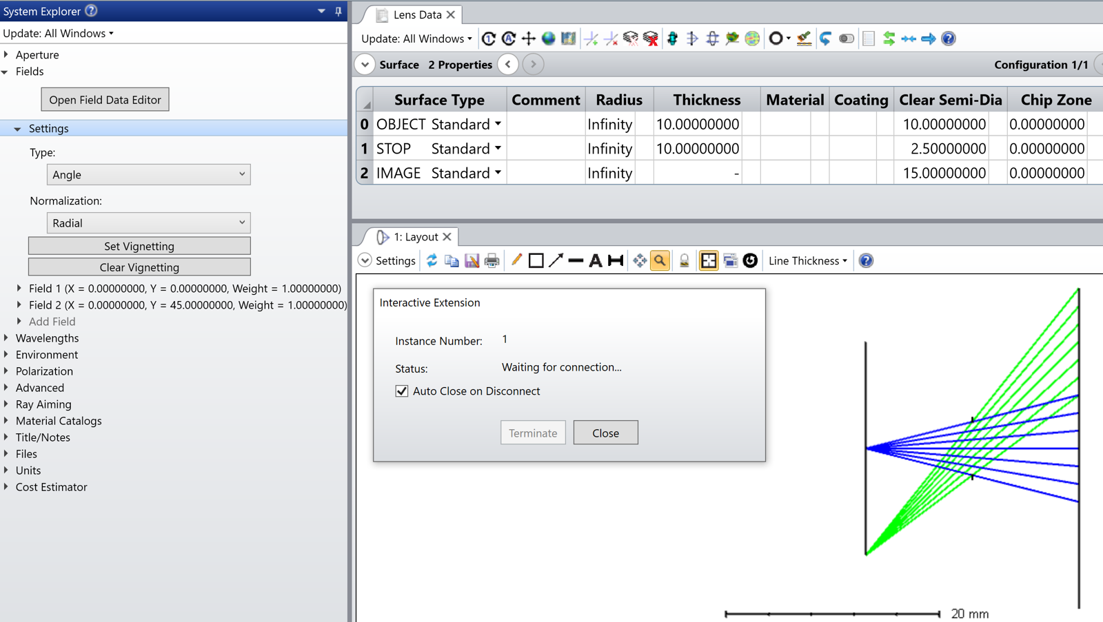
I don’t seem to be able to reproduce the issue. Assume the following system before interactive extension connection with Angle field type and a finite OBJECT Thickness:
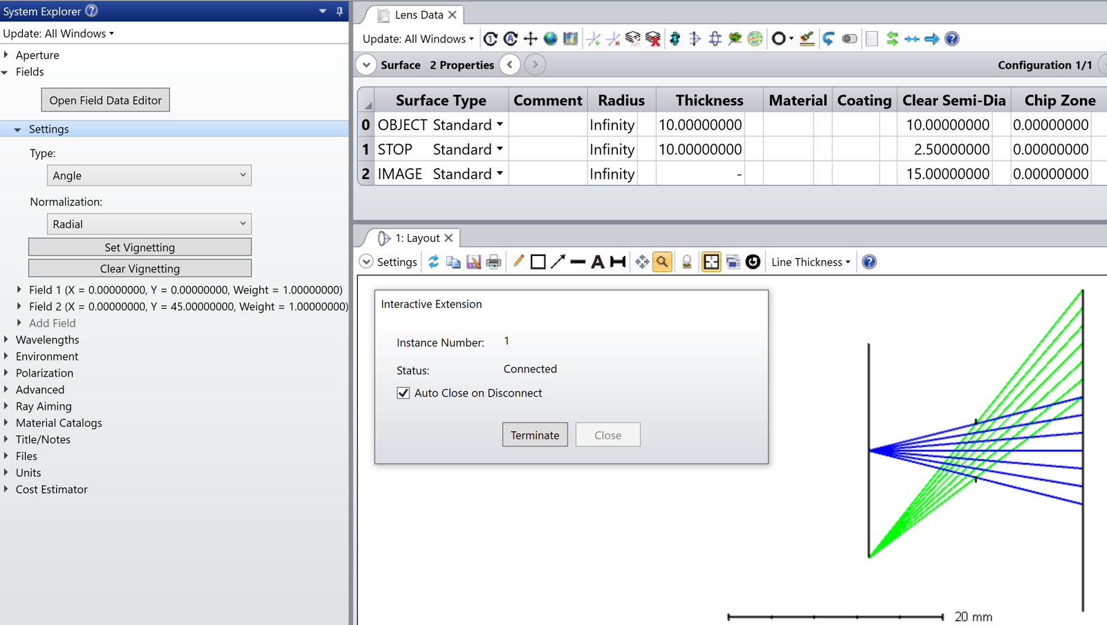
Then, the system, upon connection, remains the same for me:
As a sanity check, I ran the following command, which is True:
img_pos = [0.550,0.555,0.560,0.565,0.570,0.575,0.580,0.585,0.590,0.600,0.610,0.615,0.620,0.625,0.630,0.635,0.640,0.645,0.650] # setting position of imager from last surface of filter
# tilt_x = [0]
# tilt_y = [0]
#Loop to change decenter value and run image simulation and save file by moving to a new location
#here are the lines to run image analysis, move files to specified folder, run MTF over field analysis and defocus analysis and save them as txt files#
for first,second, in tolerance:
imager = first
#xtilt = second
#ytilt = third
object_dist = second
#ic(imager)
#ic(type(imager))
surf0.GetCellAt(3).DoubleValue = object_dist
# surf2.GetCellAt(14).FloatValue = xtilt #setting the x tilt value
# surf2.GetCellAt(15).FloatValue = ytilt #setting the y tilt value
# surf15.GetCellAt(14).FloatValue = xtilt*-1 #setting the x tilt value
# surf15.GetCellAt(15).FloatValue = ytilt*-1 #setting the y tilt value
surf13.GetCellAt(3).DoubleValue = imager #setting the imager position
I think the issue is that you are running a Design Lockdown. Please read this excerpt from the Help File about the Design Lockdown tool:
A number of steps are generally required to take a system designed in sequential mode into a production system. In particular all idealized inputs of the system must be converted into real manufacturing inputs. The Design Lockdown Tool automates this conversion by:
...
Switching from the use of image-based field point definitions (if they are being used) to object-based definitions. The primary wavelength is used for this conversion.
For finite conjugate systems, Object Height is used as the field definition.
For infinite conjugates, Angle is used as the field definition, unless the system is already using Theodolite Angles.
Systems with multiple configurations will not be converted to object-based field definitions; any analysis features or conversion to non-sequential should be manually verified if the sequential system is defined with image-based field definitions.