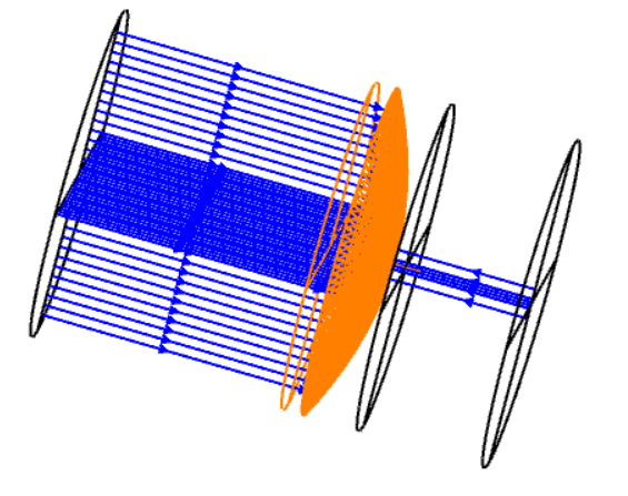
In the NSC group of a mixed mode system, I uploaded a file .step regarding a lens having mirror property. It is highlighted by the orange color in the figure below:
I was wondering if someone knows why I see only the rays passing through the hole present in the lens surface, but I am not able to visualize the rays reflected by the lens itself. They should be back reflected and focused on the lens focus.
Thank you for your answer.
Best Regards,
Aniello
Best answer by Aniello
Dear David,
I understand that to have the rays traced back after reflected by the mirrored lens one has to use the multi-configuration editor. I will take a look on it on https://support.zemax.com/hc/en-us.
My final goal is to put a second mirrored lens collecting the rays focalized by the first one. I am obliged to import a .step file regarding the first lens because it is a “deformed” lens, that is to say it has a “non-conventional” shape.
Additionally, are you aware of this from the Help File about NSC Ray Tracing in mixed mode:
This NSC ray tracing method requires the use of ports for rays to enter and leave the NSC group. Ports are described in detail in the following section about how to use NSC ray tracing in mixed mode. When using ports, rays are launched from defined field positions on the object surface, and these rays ignore source and detector objects within the NSC group. Rays must leave the NSC group via the exit port; then continue through the remainder of the sequential system.
If you still think that there is an issue with your file, please consider sharing a minimal working example with us that demonstrates the issue. I’m sure people here will be able to help you.
One word of caution, your step file gives an Error 72 in the 3D Layout if one uses the Parasolid Libraries (not sure if it is a problem really but for other people’s reference).
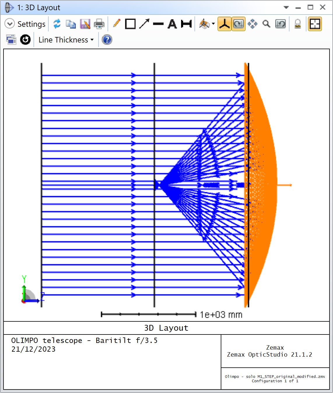
Then, regarding your problem, it is exactly the issue described in the Help File that I referrenced in my previous answer:
Rays must leave the NSC group via the exit port; then continue through the remainder of the sequential system.
You can clearly see that the reflected rays do not go through the exit port. In fact, they travel away from the exit port. There are no easy way around this caveat. If you change the exit port location such that it is before the entry port you can sort of visualize the reflected rays. This is a screenshot of your file with Exit Loc Z = -800:
The drawback is that in this situation, the rays that go through the center of the lens aperture don’t make it back to the exit port and you don’t see them anymore. Also, the rays start to travel backward because of the sign of the Thickness of Surface 3. In OpticStudio, after a mirror surface, the subsequent Thicknesses should have opposite sign, but that’s a detail.
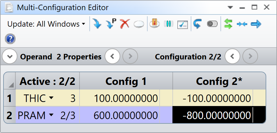
If you really want to visualize both in mixed mode, you could create two configurations where you change the location of the exit port, but you need to be carefull because the position of the next surface is dependant upon the exit port location. One solution is to define your multi-configuration as follows:
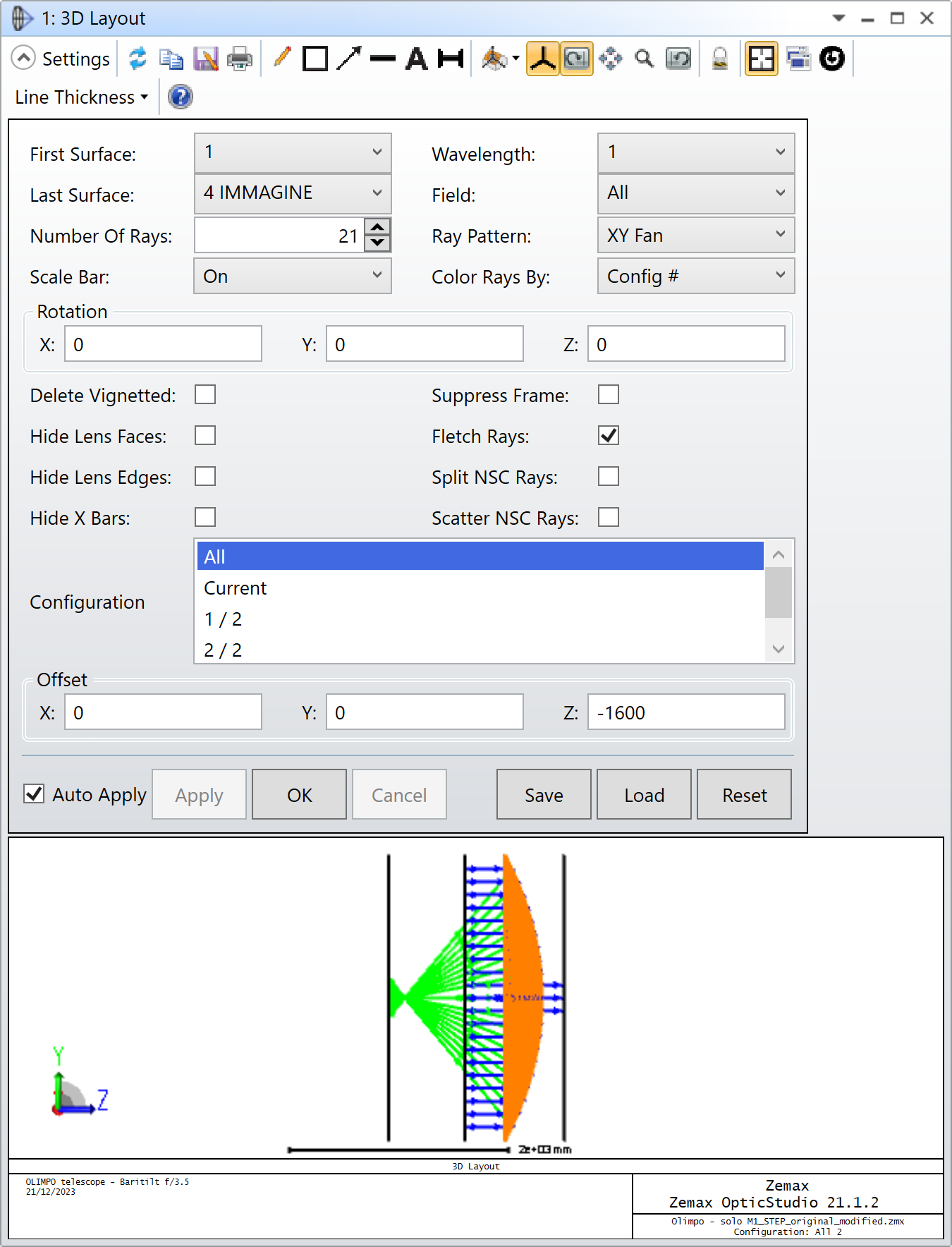
And then in your 3D Layout, you’d use the following settings:
Note the Z Offset of -1600 to account for the change in Exit Port location. Also, this is mainly for visualization purposes, depending what you want to do, there might be a better way to model your system.
Does that make sense? I’m attaching the modifed file for your reference.
I understand that to have the rays traced back after reflected by the mirrored lens one has to use the multi-configuration editor. I will take a look on it on https://support.zemax.com/hc/en-us.
My final goal is to put a second mirrored lens collecting the rays focalized by the first one. I am obliged to import a .step file regarding the first lens because it is a “deformed” lens, that is to say it has a “non-conventional” shape.