To model a diffuse surface in OpticStudio, you need to add a Lambertian scatter profile to the face of the object. Lambertian scattering will give the rays an equal probability of scattering anywhere in the unit circle - most diffuse surfaces are nearly Lambertian.


The Lambertian scatter profile can be entered under the 'Coat/Scatter' tab in the 'Object Properties' of the object you would like to make diffuse. 
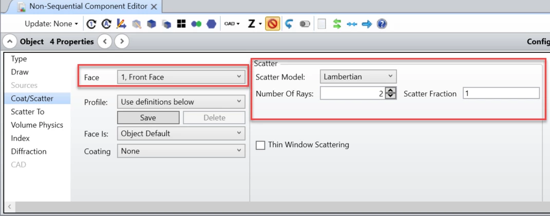


Make sure you choose the correct 'Face' that you would like the scatter profile applied to. The 'Number of Rays' effects how many scatter rays will be generated.  The scatter fraction will be the amount of power from an incident ray gets transmitted into scattered refelction/transmission vs. specular reflection/transmission. For example, if the scatter fraction is 1, the specular ray will receive zero energy and will no longer be traced; and all the energy will be divided equally among the scattered rays. If the fraction is set to 0, no scattered rays will be traced, and the specular ray retains all the original energy.


Make sure when running the ray trace to have 'Split NSC Rays' and 'Scatter NSC Rays' checked on in order to see the effects of your scatter profiles.

Dear Kaleb,


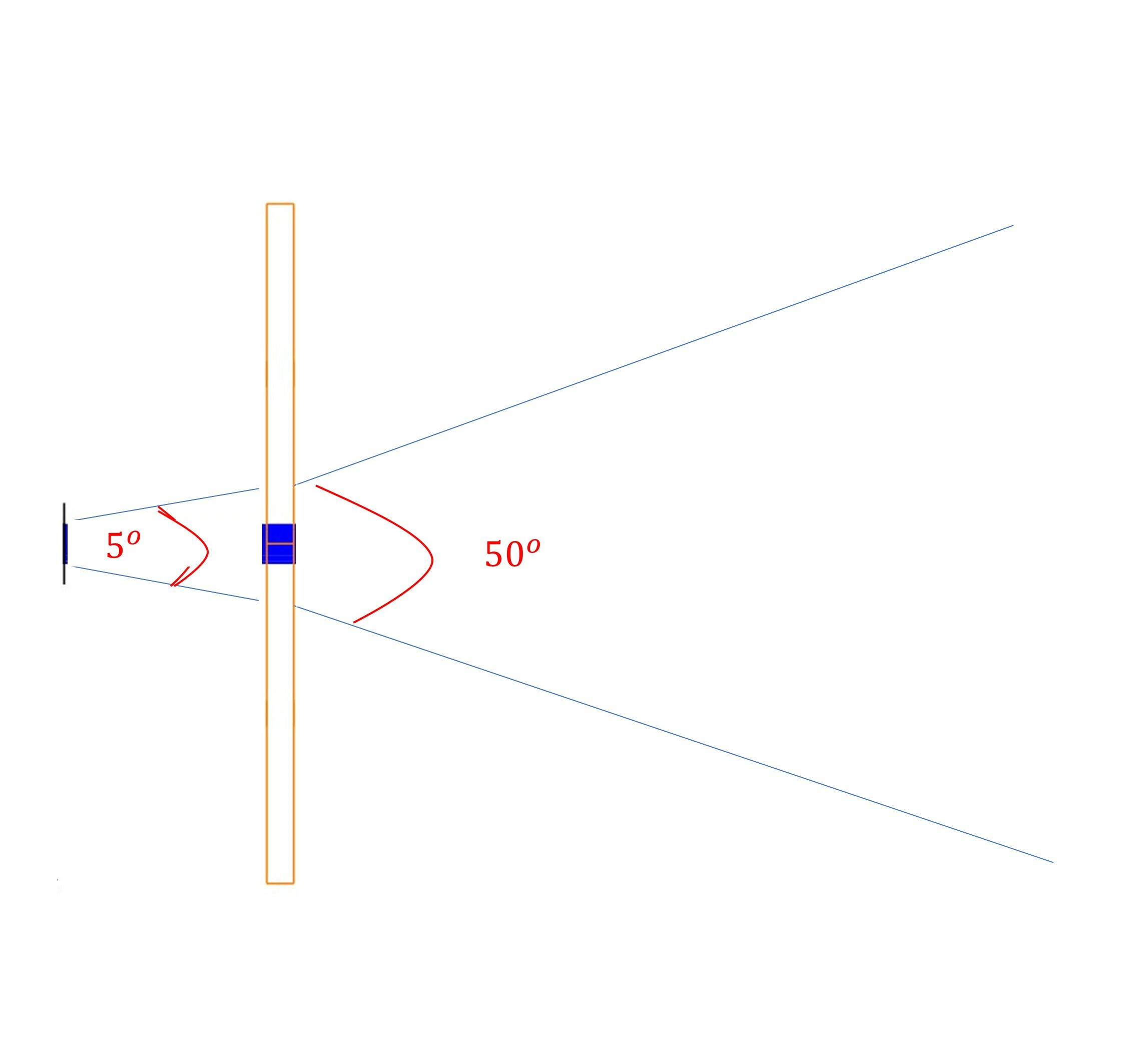
I have some doubt and it will be great to me to hear from you and will be very thankful to you. I am using Zemax Non-sequential mode to model the diffuser to convert the HPBW of the source form 5 to 50 degrees. is it possible to do in Zemax as you have suggested above. I am attaching the drawing for what I want to achieve? pLease have a look


Best


Faheem Ahmad

raydiagram.jpg

Dear Kaleb,


I understand that the lambertian scatterer can scatter the incident ray uniformly.


But suppose I add a metal coating on the face and then apply a lambertian scatterer with 'number of rays = 1' and 'scatter fraction = 1', the direction of the reflected light will follow lambertian distribution, but how about the intensity of the reflected light? assuming the metal coating has a reflectance of 0.9 and incident ray has power of 1W, will be power of the reflected ray be 0.9W(independent on the angle)?


thanks!


Hi Xiaoning,


If the fraction to scatter is 1.0, the ray always scatters, so 100% of incident ray energy will be scattered after first accounting for attenuation by the coating. So in your case, the reflected energy will be 0.9W.


How OpticStudio treats this value depends upon whether or not Ray Splitting is turned on. If ray splitting is off, all of the energy of the ray follows the randomly generated scatter path (The number of scatter rays has no affect if ray splitting is off). If ray splitting is on, then OpticStudio will split the specular ray into one or more scattered rays, while still possibly tracing the specular ray. The specular ray will receive a fraction of the original energy equal to (1.0 - f) where f is the fraction to scatter. The remaining energy will be divided equally among the one or more scattered rays. The number of scatter rays determines how many scatter rays will be generated. For example, if the fraction to scatter is 1.0, then the specular ray will receive zero energy and will no longer be traced; and all the energy will be divided equally among the scattered rays.


You may find useful this article that explains how to model a partially reflected/partially scattering surface.


Best,


Berta


Hi Berta,

thanks very much for your explaining about scatter and how to zemax treats the “scatter box” to simulate. 

Do you know if there is any documentation about how many scatter rays must be taken into an account when a scatter surface is simulated? Is there any reference value? what is the dependency between the number of scatter rays and type of material when scattering is defined?  Where could i find information about how to choose an aproppiate number of rays for a defined material with difusse behaviour?


thank you very much in advanced,

SoniaP


Hello Sonia

We don’t have any documentation on how to select the number of scattered rays. I think it will depend on your system, the number of rays sent by the source and received by the scattering surface, the detector signal to noise ratio. 

You can simply run some tests and see how your results change with the number of scattered rays.

Or you can add a detector to check the distribution of rays after the scattering surface.

Sandrine


Hello Sandrine,

thanks you very much for your help.

We will try to run test as you recommend

SoniaP


Dear all,

we have performed a simulation with a lambertian surface and we have noticed a strange behaviour. 

We suppose that the more scatttered ray the more the energy is shared among the number of rays, so we suppose that the more scattered ray the less is the energy from each ray and in that case the irradiance value near surface would be lower.

That behaviour is shown as we increase the N rays (lambertian coating) but, when the N rays is upper than a certain value, the irradiance value is bigger that expected ( increasing instead of decreasing).

Could you tell us what is the problem? I am stuck :P


thank you very much for your support


Hey Sonia

Do you have a simple file that you could share here (it will need to be a zip)? Thank you.


Reply