How to get the dimensions of a STEP-object in NSQ mode?
Hi Guys!
Is it possible to get the dimensions (height, width, position, etc.) of a STEP-object from within Zemax in NSQ-mode?
Background: I have a STEP-object imported which actually is a mirror mount. Now I’d like to toggle between this and another mount, very similar, but slightly different in height. There are a couple of other objects following the mirror mount and currently, whenever I change the STEP-file, I need to manually adjust the position of the other objects, according to the height of whichever mount I use. Is there a way to get the height of the STEP-object (or the position of single face, surface, etc. of the STEP-object), and use it as a pickup for the position of the following objects?
The two objects have the same coordinate system, so it is really only one dimension which I need to get. This could for example be the height of the bounding box, of the z-coordinate of the top surface, or something else. Is there a way to get any STEP-object property?
Thanks!!!
Best, Peter
Page 1 / 1
Hi Peter,
There are some ways of gettting the dimensions of a STEP object in OpticStudio. This is generally done by tracing rays and checking where they intersect with the object. This is what the Analyze..NSC Sag is using I believe. This is based on @MichaelHknowledgebase article.
That being said, in your particular case, you seem to know the height difference and the two object share the same coordinate system. Therefore, I think there’s a much easier solution by leveraging the Multi-Configuration Editor and the Ref Object column.
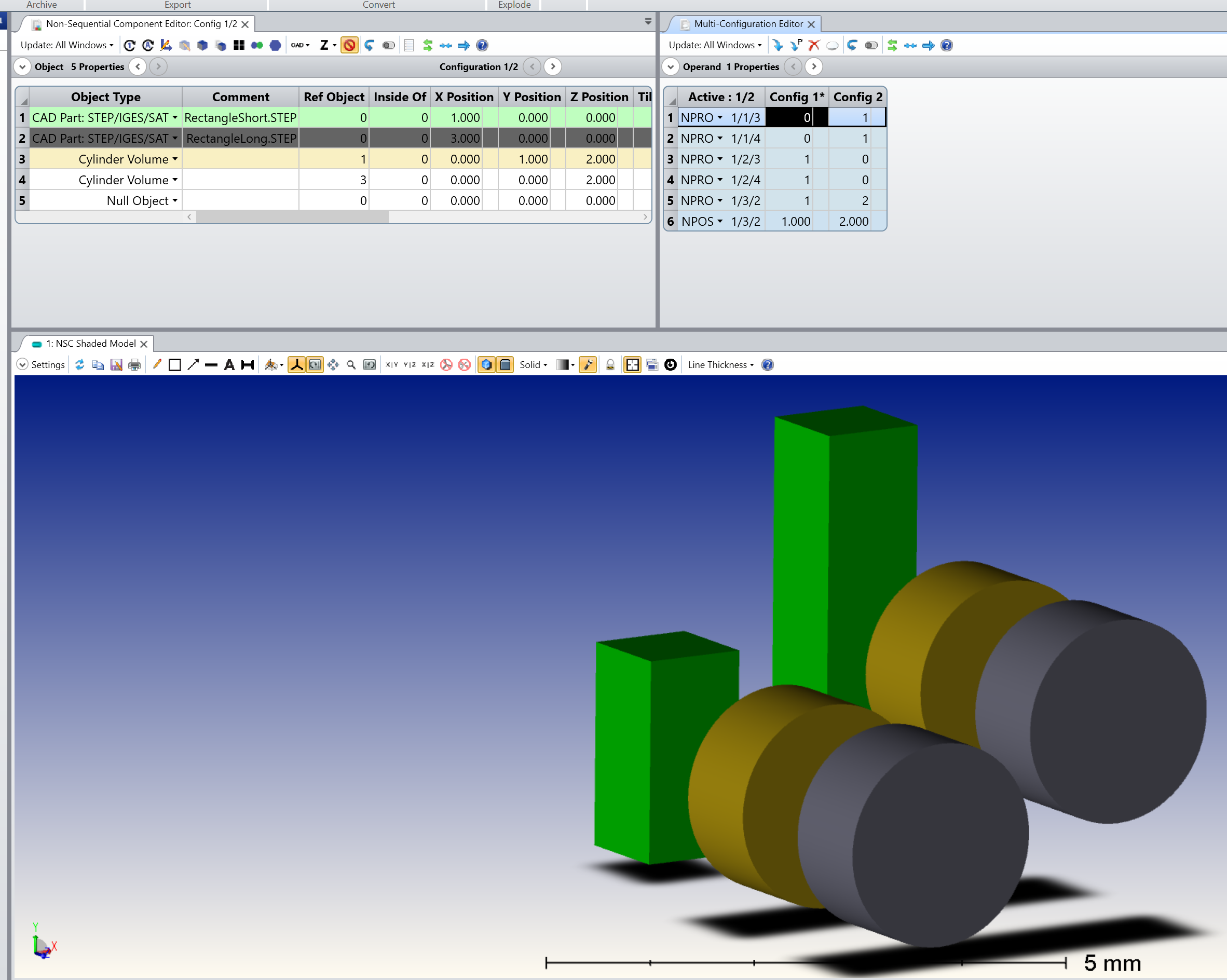
I made a simple example with two STEP files representing rectangular volumes of different length (this example is also attached to my reply):
The idea is to have your two step files at the same time in the Non-Sequential Component Editor. However, you can use the Multi-Configuration Editor to have one configuration in which you ignore one STEP, and another configuration where you ignore the other STEP (hopefully that make sense). The way to do that is to use NPRO to control the flags: Do Not Draw Object, and Rays Ignore Object, these are the Multi-Configuration operands 1-4. Next, I use NPRO again (Operand 5) to control the Ref Object of my first Cylinder Volume. In Configuration 1, I reference the cylinder to the short rectangular volume, and in Configuration 2, I reference it to the long rectangular volume. Finally, I adjust the height of the Cylinder Volume with NPOS (operand 6) such that the Cylinder Volume axis is at half the height of the STEP files.
Notice that if the subsequent object, such as the gray Cylinder Volume, are referenced to the yellow Cylinder Volume, they adjust their position automatically.
Let me know if that helps, and take care,
PS: I did put a X Position on Object 2 such that you can visualize the two configurations side by side, and it also illustrates how the Ref Object column works.
David
Works like a charm!!!
Hi David, thanks a lot for your answer. Why didn’t I think of the Multi-Configuration feature myself?! You’re quite right: I do know the size of the component, so setting it up with two configurations and using the NPRO and NPOS operands was straightforward. Sometimes it only takes a little nudge. Thanks for that and your help. Much appreciated.
Have a good day!
Best, Peter
That’s odd. Your answer should be “best answer”. Not mine. Hmm.
Hi Peter,
My pleasure. I think only Zemax staff can change the best answer. Perhaps @Allie can do it?