When creating a thermal configuration, all semi-diameters, chip zones, and mechanical semi-diameters are set to a fixed value with thermal pickups on the subsequent configurations. This creates problem in optimization where the the diameters need to change. In particular, this can result in unwanted vignetting. I would like to keep the base thermal configuration with the automatic clear semi-diameters solve, but that option isn’t populated in the multi configuration editor.
I could see using a ZPLM solve, but I couldn’t identify an operand to set the automatic clear semi-diameter. Or really any operands relating to a surface diameter and vignetting… Maybe I missed it?
Any advice would be greatly appreciated!
Thank you,
John
Best answer by MichaelH
Hi John,
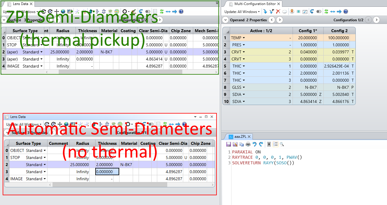
OpticStudio historically has confusing rules around apertures and semi-diameters (adding a Chip Zone and Mechanical Semi-Diameter did not help this situation either). There are several behind-the-scenes calculations which occur every time the “optical system” is updated and the order of these calculations matter (i.e., you need to calculate the paraxial entrance pupil before you can trace the paraxial marginal ray for something like F/# or Pickup Solves can only reference surfaces before the current surface, not after). My guess is that the Thermal Pickup calculations rely on a “fixed" nominal system and having values in the MCE which rely on ray tracing (which the automatic semi-diameter relies on) complicates the calculation; for “easy” systems (axial rotationally symmetric imaging systems), the thermal code might be able to handle automatic semi-diameters, but my guess is once you get into even slightly complex systems (buried stop, non-symmetric, or folded systems), the thermal code has to use a fixed semi-diameter.
With that said, if you have an “easy” system, you can create a ZPL Solve on the SDIA in the MCE and use RAYY() to mimic the automatic semi-diameter code:
PARAXIAL ON
RAYTRACE 0, 0, 0, 1, PWAV()
SOLVERETURN RAYY(SOSO())
This code will perform a paraxial ray trace on-axis +py marginal ray and return the Y coordinate for the defined SDIA operand in the MCE (I have removed the CHZN and MCSD operands because these should not be needed during the initial optimization process where the semi-diameters are greatly changing and this also just complicates the goal). This results in less than a 0.7% difference in the automatic semi-diameter for a thermal singlet:
I’m not so familiar with thermal designs so I’m not sure I understand your problem.
This is what I understood from your question, let me know if I got it wrong: you want to keep the SDIA operands in the Multi-Configuration Editor, but you want to remove the Thermal Pick-up solves (those will then become automatic solves). To the best of my knowledge, those Multi-Configuration solves can’t be accessed with ZPL. However, this can be done with the ZOS-API. Here is a Python snippet:
OpticStudio historically has confusing rules around apertures and semi-diameters (adding a Chip Zone and Mechanical Semi-Diameter did not help this situation either). There are several behind-the-scenes calculations which occur every time the “optical system” is updated and the order of these calculations matter (i.e., you need to calculate the paraxial entrance pupil before you can trace the paraxial marginal ray for something like F/# or Pickup Solves can only reference surfaces before the current surface, not after). My guess is that the Thermal Pickup calculations rely on a “fixed" nominal system and having values in the MCE which rely on ray tracing (which the automatic semi-diameter relies on) complicates the calculation; for “easy” systems (axial rotationally symmetric imaging systems), the thermal code might be able to handle automatic semi-diameters, but my guess is once you get into even slightly complex systems (buried stop, non-symmetric, or folded systems), the thermal code has to use a fixed semi-diameter.
With that said, if you have an “easy” system, you can create a ZPL Solve on the SDIA in the MCE and use RAYY() to mimic the automatic semi-diameter code:
PARAXIAL ON
RAYTRACE 0, 0, 0, 1, PWAV()
SOLVERETURN RAYY(SOSO())
This code will perform a paraxial ray trace on-axis +py marginal ray and return the Y coordinate for the defined SDIA operand in the MCE (I have removed the CHZN and MCSD operands because these should not be needed during the initial optimization process where the semi-diameters are greatly changing and this also just complicates the goal). This results in less than a 0.7% difference in the automatic semi-diameter for a thermal singlet:
Thank you for the detail in your response and being candid about the confusing diameter settings in OS.
Subsequent to my post, I had the same idea you suggested to automate setting semi-diameters in the MCE with a ZPL, with one difference that I used a skew ray [RAYTRACE0,1,0,-1] to estimate diameters needed for off-axis fields. My system is simple (rotationally symmetric, 5 elements). This method works, but unsurprisingly slows down the optimization.
What I ended up doing was creating a script to output a list of the diameters (using the same raytrace methos) and used it intermittently between optimizations to adjust the diameters.
I’m interested to hear if others have found better practices…
I must say, I don’t see why OS couldn’t support the Automatic solve on SDIA operands in the multi-config editor. Maybe someone from support or development could clarify whether this could be supported. Until then, yes you’ll need a macro solve to do what the automatic semi-diameter solve does.
That said, thermal analysis is intended for a later stage of the process than the initial design shape stage. I would recommend delaying thermal analysis until your design candidate has an agreed shape: say a Cooke versus a Tessar. If you’re stil trying to decide between a doublet, Cooke and Tessar (or whatever) and the overall shape of the design is changing drastically, then I’d say it was too early to worry about thermal. But I’m sure you know what you’re doing 😀
I would be interested in knowing more about your system and temperature range. It does sound odd for a thermal analysis to introduce vignetting at one temperature but not another. It does sound like it’s being used a bit too early, but I’d love to know more.
I understand the problem now! Sorry for my inadequate answer. Could you have a dummy surface before the surface that has the SDIA operand, and pick-up the clear semi-diameter of that surface (that isn’t in the MC editor and has the automatic calculation)? That is a harsher approximation (compared to @MichaelH answer) of the actual clear semi-diameter, but it might be faster to compute than RAYTRACE. The issue is the curvature of the surface.
I was doing a material search for a better athermal performance. With different materials the thicknesses were changing enough to introduce some vignetting. The optimizer exploits that vignetting and when you open the apertures later there is a lot of aberration introduced. Additionally, the diameter affects the CTE changes and thermal performance, hence my effort to have the automatic adjustment. I agree this is a non-issue if you have your from and materials stable.
As you say, this would seemingly be a supported feature and wanted to check with the community that I wasn’t missing something. Sounds like it might be a feature request.