Solved

How to explain the location of the object principal plane in a thick plano-convex lens

  • October 2, 2024
  • 9 replies
  • 564 views

David.Nguyen
Luminary
Forum|alt.badge.img+2

From reading this interesting discussion below.

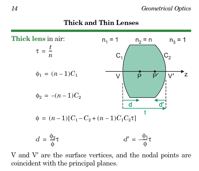
I went down a rabbit hole when I was figuring out where the object principal plane of a thick plano-convex lens is. I’ve been taught to find the principal planes like its described at RP Photonics, that is:

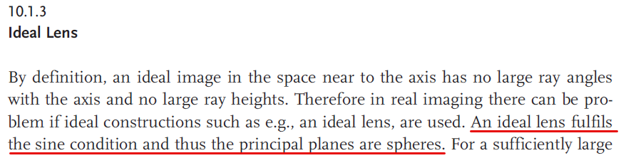
extrapolate the ingoing and outgoing rays such that they meet in a plane

However, when rays parallel to the optical axis enter through the plane face of the lens, the ingoing and outgoing rays will meet exactly along the convex face, which is not a plane.

Therefore, I believe the principal plane is defined as the plane coincident with the convex surface vertex. At least, this is what I’ve taken away when I used OpticStudio (surface 1 is the convex surface).

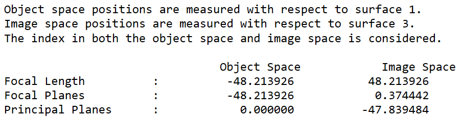
I also found this information here:

Plano-convex and plano-concave lenses have one principal plane that intersects the optical axis, at the edge of the curved surface, and the other plane buried inside the glass.

I can accept this definition, but I was curious, from a teaching perspective, to hear if someone can provide an explanation that would be compatible with the “traditional” explanation: find the plane where the in and out rays bend. I know we are at a boundary between paraxial and real optics and it might not make sense to ask this question, but I could imagine a student asking about this and all I could answer for now is that in this instance we choose the vertex of the convex surface as the principal plane and its a special case.

Take care all,


David

Best answer by MichaelH

Hey David,

I think you’re on the right track with real vs paraxial rays.  When I encounter a basic question like this, I always like to go back to the fundamentals, namely how are the principal planes truly defined (not simply how are they calculated).

Principal planes (along with all the Cardinal Points) are defined using Gaussian optics.  From the Field Guide To Geometric Optics:

Gaussian optics treats imaging as a mapping from object space into image space.  It is a special case of a collinear transformation application to rotationally symmetric systems, and it maps points to points, lines to lines and planes to planes.

Therefore, when you take a real system and Gaussian reduce it (so you can use concepts like Lens Maker’s equation, reduced distances, magnification), there are no curved surfaces but only points, lines, and planes.  This is where thin lens and paraxial optics comes from.

From a calculation standpoint, I believe all the Cardinal Points in OpticStudio use paraxial ray tracing, so the curved surface is actually a plane.  Another way to think of it is you calculate the Principal Plane using parabasal rays that are so close to the optical axis the local curvature of the lens looks like a vertical plane.

Something that would be really nice from a teaching perspective is if OpticStudio had the ability to show Paraxial Layouts…then the calculation would become visually obvious.  

View original
Did this topic help you find an answer to your question?

9 replies

MichaelH
Ansys Staff
Forum|alt.badge.img+2
  • Ansys Staff
  • 358 replies
  • Answer
  • October 2, 2024

Hey David,

I think you’re on the right track with real vs paraxial rays.  When I encounter a basic question like this, I always like to go back to the fundamentals, namely how are the principal planes truly defined (not simply how are they calculated).

Principal planes (along with all the Cardinal Points) are defined using Gaussian optics.  From the Field Guide To Geometric Optics:

Gaussian optics treats imaging as a mapping from object space into image space.  It is a special case of a collinear transformation application to rotationally symmetric systems, and it maps points to points, lines to lines and planes to planes.

Therefore, when you take a real system and Gaussian reduce it (so you can use concepts like Lens Maker’s equation, reduced distances, magnification), there are no curved surfaces but only points, lines, and planes.  This is where thin lens and paraxial optics comes from.

From a calculation standpoint, I believe all the Cardinal Points in OpticStudio use paraxial ray tracing, so the curved surface is actually a plane.  Another way to think of it is you calculate the Principal Plane using parabasal rays that are so close to the optical axis the local curvature of the lens looks like a vertical plane.

Something that would be really nice from a teaching perspective is if OpticStudio had the ability to show Paraxial Layouts…then the calculation would become visually obvious.  


Jeff.Wilde
Luminary
Forum|alt.badge.img+3
  • Luminary
  • 505 replies
  • October 3, 2024

I agree with Michael.  The principal planes (and more generally the cardinal planes), are paraxial entities.  In a paraxial world, all lens surfaces are planes that have ray-bending optical power.  The planes reside at locations calculated relative to where the lens surfaces intersect the optical axis.  Paraxial ray tracing is very valuable; for example, the Seidel aberrations are computed by tracing the paraxial marginal and chief rays.  In Zemax, rays don’t have to be small-angle to be considered paraxial.  Instead, rays that are traced using linearized paraxial math (i.e., linearized Snell’s Law, again with lens surfaces represented as planes), are called paraxial. 

A good reference is Introduction to Lens Design, by J. M. Geary, Ch. 4 (Paraxial World).

Regards,

Jeff

PS: I also agree with Michael that having a paraxial ray trace layout window would be very nice!


David.Nguyen
Luminary
Forum|alt.badge.img+2
  • Author
  • Luminary
  • 1113 replies
  • October 3, 2024

Thanks @MichaelH and @Jeff.Wilde. You gave me a different perspective on this problem. I like the idea of using parabasal rays. I also find paraxial ray tracing to be extremely valuable and its interesting to see how paraxial ray tracing subtly integrates with real ray tracing into OpticStudio.

On a side note, @Jeff.Wilde have you ever considered sharing a curated reading list for optical design/engineering? You always have the right references and you point people to the exact chapter/section that they need. Your knowledge of the literature on this subject is a literal treasure trove for the community.

Take care,


David


Jeff.Wilde
Luminary
Forum|alt.badge.img+3
  • Luminary
  • 505 replies
  • October 4, 2024

@David.Nguyen

Thanks for your gracious comments.  I haven’t thought about putting together a reference list organized by topic.  Maybe that’s something I’ll work on in the future.

Speaking of references, I think most optical engineers know about the SPIE Field Guides.  They are very handy, concise handbooks chocked full of good information.  For example, the principal planes/points for a thick lens are succinctly described in the SPIE Field Guide to Geometrical Optics by J. E. Greivenkamp.

From this description it is clear that the principal planes (at P and P’) need not coincide with the physical lens surfaces.  However, for plano lenses (with one of the two surfaces being a flat), then one of the principal planes does coincide with a lens surface.  Here’s a nice figure from Fundamentals of Optics, 4th Ed. by Jenkins & White:

Regards,

Jeff


Jim Skippy Brookhyser

I have struggled with this in the past (and in the present) as well.

My current conceptual understanding is that the principal surface need not be a plane. Maybe someone can verify?

If I’m correct in this, then what I want from Zemax analysis is to be able to show me where the principal surface is, and what its shape is. Maybe I want to optimize its shape and location for my application. Maybe I need a picture of the principal surface to communicate system behavior with colleagues working on the system from other disciplines.


Jeff.Wilde
Luminary
Forum|alt.badge.img+3
  • Luminary
  • 505 replies
  • January 18, 2025

@Jim Skippy Brookhyser:

Yes, it is indeed the case that outside of the paraxial regime the principal planes become curved.  Here is an example as provided by Warren Smith in his book Modern Optical Engineering, 3rd edition.

As Smith notes: “In a well-corrected optical system the principal surfaces are spheres, centered on the object and image. In the paraxial region where the distances from the axis are infinitesimal, the surfaces can be treated as if they were planes, hence the name, principal “planes.” The intersection of this surface with the axis is the principal point.” 

In my estimation, the figure above is actually a little bit deceiving.  If the lens is being used to focus an incoming collimated beam, then the first principal surface is planar and the second principal surface is spherical.  Likewise, if the lens is being used to collimate a point source, then the first principal surface is spherical and the second principal surface is planar. 

In any event, the above figure does convey the fact that principal surfaces can be curved -- while it should be recognized that for a given lens the principal surfaces change their curvatures depending on where the local object and image points are located, which in turn are determined by the manner in which the lens is designed and used.  Here is a simple illustration for finite-conjugate imaging with an ideal thin lens taken from the Handbook of Optical Systems, Vol. 1 by H. Gross.


Lastly, the notion of spherical principal surfaces only applies to an ideal lens or at least a well-corrected lens -- i.e., one that can yield stigmatic imaging at a specific magnification.  Otherwise, it’s not clear how one would define the principal surface shapes or why they would be needed in the first place.

More detail can be found in: Ray-tracing model of a perfect lens compliant with Fermat’s principle: the Cardinal Lens

Regards,

Jeff


Jim Skippy Brookhyser

@Jeff.Wilde thanks for the reply! That description and the references are really helpful.

I see what you’re saying about how Figure 2.1 from Smith’s work is misleading. When I think of a telescope as an example, the concept in my head differs from how you clarified it. The light from distant objects like stars is about as collimated as one can find. Let’s say my telescope is designed to have a wide field of view, and also produce a flat image for a conventional camera sensor. If the aperture of this telescope is placed at the front focal point of the lens, then my intuition tells me the front principal plane would be curved and generally centered on the front focal point, while the back principal plane would be flat, so that it is parallel to the camera sensor. Does that sound right, or did I miss something?

Lastly, I’m still trying to figure out how I can use Zemax to illustrate the principal surfaces in a helpful way in my application. If I figure it out and still have extra time, maybe I’ll be able to put together a toy example without proprietary company information to share here. Don’t hold your breath.

Edit: Ok, I have to admit my telescope example might not seem realistic. It looks a lot more realistic if instead you consider the real-life situation of a telecentric scan lens setup for a laser beam with scanning mirrors.


Jeff.Wilde
Luminary
Forum|alt.badge.img+3
  • Luminary
  • 505 replies
  • January 24, 2025

@Jim Skippy Brookhyser :

I think your intuition may not be correct, but perhaps you can explain further.

Again, if you refer to Smith’s comment:  “In a well-corrected optical system the principal surfaces are spheres, centered on the object and image.”  If the object is at infinity, the first principal surface must be planar, while the second principal surface is spherical with a radius of curvature centered on the image point.

I assume you have not looked at the paper I referenced above.  There you will find various examples of spherical and planar principal surfaces.  For a given lens, each pair of local object/image field points corresponds to a unique set of principal surfaces.  With a little effort, they can be drawn -- Fig. 8 in the paper provides one example:


This paper explains why the principal surfaces are fundamental to ray tracing through an ideal lens.  All of the Zemax models discussed in the paper are provided as open-access supplemental files:


Regards,

Jeff


Jim Skippy Brookhyser

@Jeff.Wilde Yep! reading that paper does clarify a ton of stuff. Thanks for the paper, and thanks for the DLL too! I expect me and my coworkers will be using it quite a bit going forward. I really appreciate it.


Reply


Cookie policy

We use cookies to enhance and personalize your experience. If you accept you agree to our full cookie policy. Learn more about our cookies.

 
Cookie settings