I'm trying to create a prism in the software, using sequential mode, and encountering some issues. But I have since found an example that does some things differently, so maybe there is a way forward.
Basically, light enters a prism through a wall, at 90deg, and then encounters a 45deg wall, that will induce total internal reflection. But instead of simply coming out of the other flat surface, my device will have a lens on that side, and a much longer path. All of this is being done inside a solid. Meaning, no joined parts or anything. Just one big block of material.
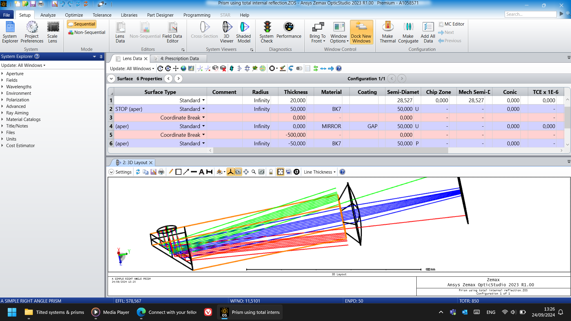
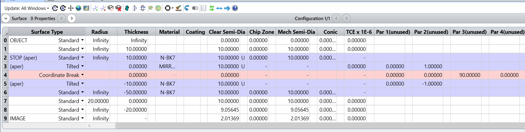
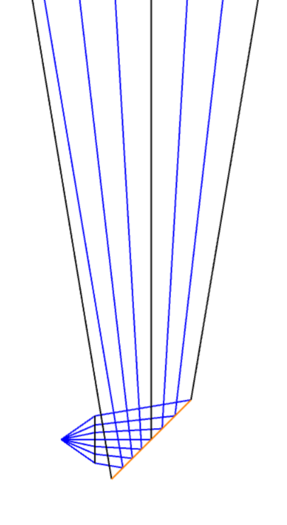
I took the sample and edited it to approximate my desire. All dimensions are exaggerated.
The thing is, when i tried to do it, I encountered some problems. Although i can start to see why, based on the sample, that I didn't make use of distances in the coordinate breaks. Also, in my simulation, I kept having erratic and non repeatable results in terms of efficiency.
And as you can see, my prism is "inside" my lens, of sorts. I seem to not have designed it in the right way and that may be the reason why I'm not getting good results.
For context, I have all those coordinate breaks to try and simulate loss in performance due to variations in angles.
What would you advise I change to get this to work? What should I learn about coordinate breaks and how they work here?
How can I create this prism so that it becomes one continuous solid with a lens at the end?
All help is appreciated.
Thank you.
Best answer by David.Nguyen
@Tiago117 and @Yang.Yongtao,
Very interesting discussion. Please allow me to give you my 2cts.
First, when @Yang.Yongtao writes:
I guess the material of surface after mirror is air ,so the solid cannot be got.
I think it is not correct. If you look at the Help File in the section Conventions and Definitions » Glasses, you can read the following excerpt:
The index of refraction of the mirror space is always equal to the index of refraction of the media before the mirror
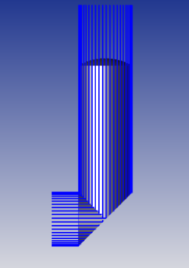
In fact, if you don’t use apertures, a volume is created in the Shaded Model.
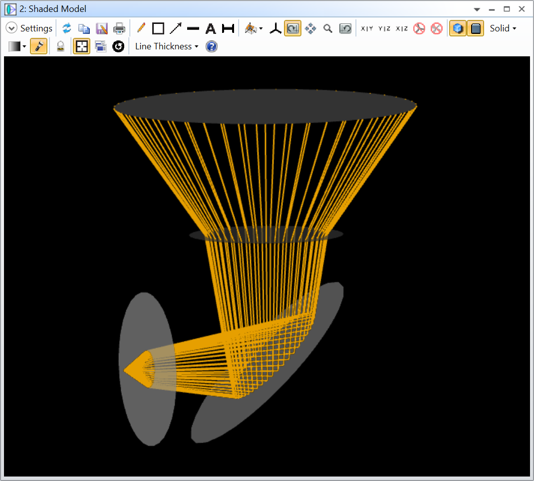
The problem comes when you apply apertures. The surfaces are not combined to form a volume anymore. However, we can still see the refraction happening in and out of the prism.
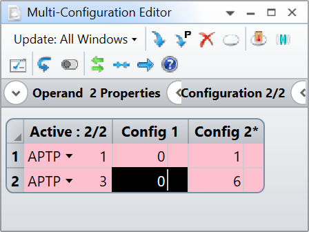
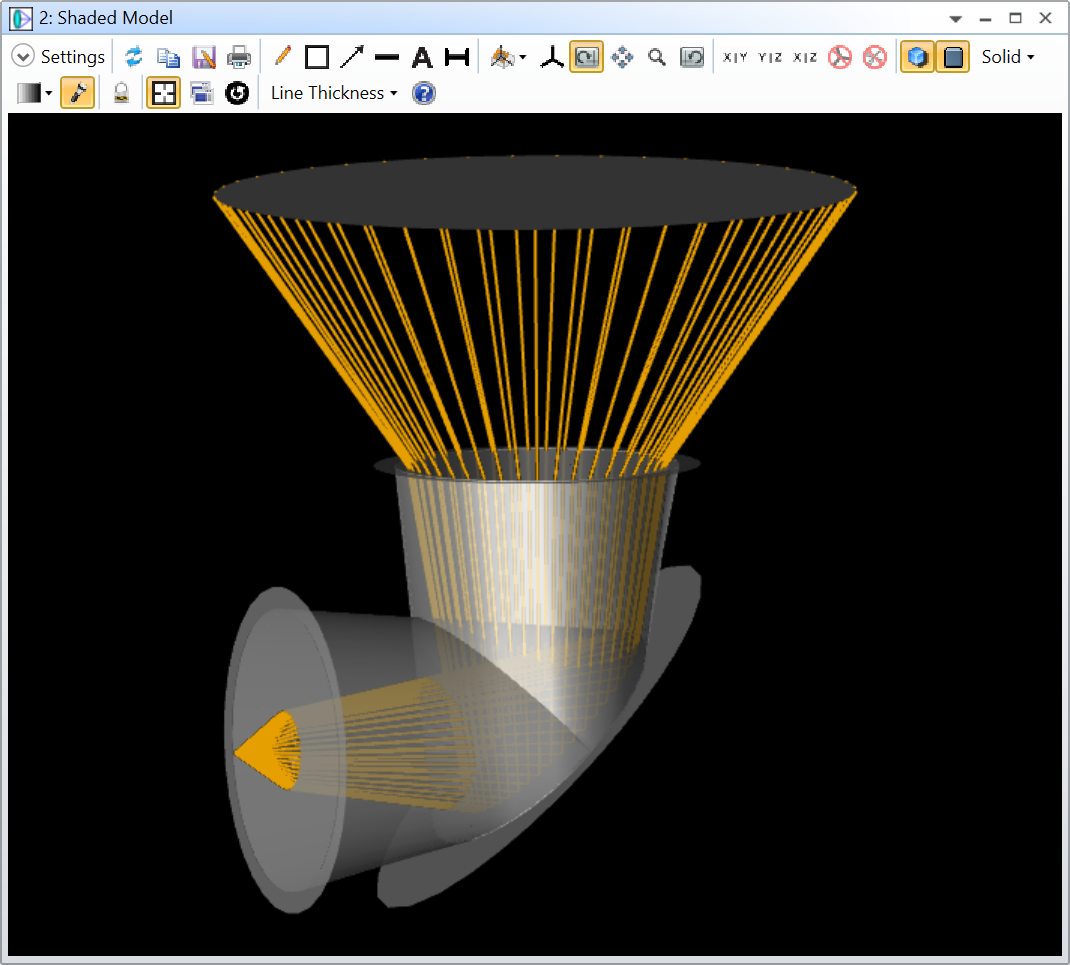
Why is the volume not created? I don’t know. But the rays are traced exactly in the same way. If you need to convince yourself, you can setup a Multi-Configuration system where one configuration doesn’t have apertures and one has apertures. Then, you can display both configurations in the same Shaded Model, and color the rays by configuration.
We only see the orange rays from the first configuration because rays from the second configuration perfectly overlays with them. You can further convince yourself by adding an X Offset to the Shaded Model to see both configurations side-by-side.
And this finally brings me to the point I wanted to address here.
Model Accuracy vs Appearance
In OpticStudio, and this is probably also true for other design/simulation softwares, there’s a distinction to be made between what a model does and how it looks like. Quite often, we have this expectation that our model should have a realistic appearance to be accurate. However, these are two different goals that are sometimes not compatible with each other. Personally, I make the most simple models for calculations and when needed, I translate those models into visually appealing ones (for presentation, rendering, or drawing).
Going back to your particular case, it seems like having a “good-looking” prism in pure sequential mode will be difficult. There are several possibilities. You could solve your design problem with a not “good-looking” but still accurate sequential prism, and then based on this model, make a non-sequential prism that you can use for rendering. That way you can perform all your sequential analyses and still have a way to display the prism should you need to. Or, you could use the mixed mode (Non-Sequential component in Sequential mode), that would allow you to model the prism in Non-Sequential and include it in a Sequential model using the Non-Sequential Component surface. This will look better visually, but there are some limitations. It all depends on what you want your model to do. Setting up a mixed-mode system can be a bit challenging at first, I recommend reading those articles:
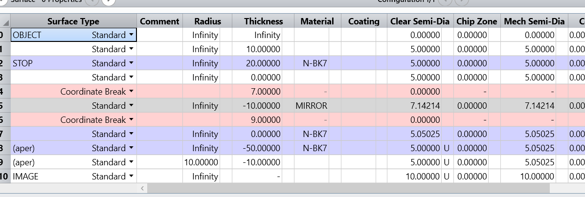
I’ve made a dummy example (see below), that I will also attach to my answer.
Notice that I’ve used a Boolean Native object to make the volume a single volume, but its again a visual trick and down the line it could slow down the ray tracing as explained in this article:
This illustrates once again that having a “good-looking” model and one that does the job is sometimes not a good idea because these endeavors compete with one another.
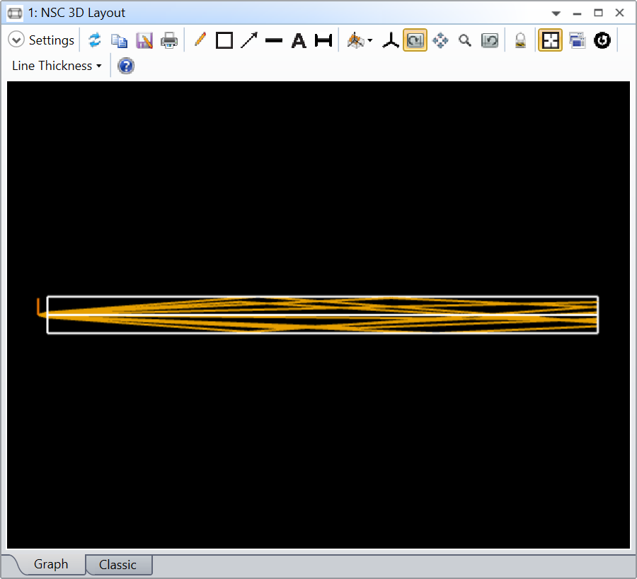
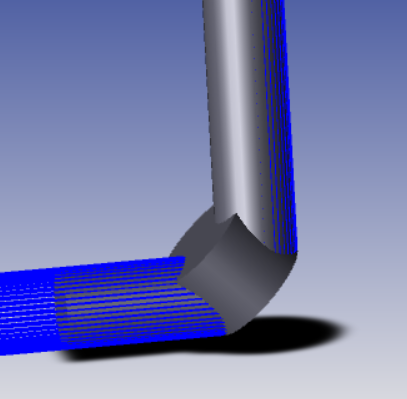
Another thing to consider is that in Sequential mode, rays must go from one surface to the next. While it might look like you have a volume, the rays will not interact with the walls of your prism. In the example below, I just have a long cylinder of SILICON.
As you can see the rays go through the cylinder walls unperturbed and they are simply terminated at the vertex of the cylinder end face. This wouldn’t be the case in Non-Sequential where some would be reflected (TIR).
This will be important for your simulation of loss. In the sequential case, the rays are terminated and will be lost. In the non-sequential case, the rays could TIR and somehow make it to the other end of the prism.
Once again, its all a matter of what you want to achieve.
Sorry for the long post, its a subject dear to my heart.
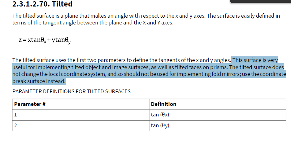
It seems you followed a different approach to that of the example. You used tilted surfaces instead of 2 coordinate breaks. How are those different? And which one is better to simulate a full solid?
Also, it seems in my own example, the mistake I did was not creating any thicknesses in the coordinate breaks. And I think, for my case, the software just made mirrors inside of mirrors, all overlapping. Would that be a fair assumption?
Thank you.
Hi Tiago
I have also tried the coordinate break method
and just in my opinion, coordinate break is good choice for fold mirror but not for element with inner mirror surface.
that’s all I am have considered, and lets wait others’ reply.
I never considered tilted surfaces but perhaps that might be the best option.
But also, my light is straight from the source, so diverging. It's not collimated. So when the beam diverges, the software expands the volumes to match it and then creates weird shapes. As you can see in my example.
I never considered tilted surfaces but perhaps that might be the best option.
But also, my light is straight from the source, so diverging. It's not collimated. So when the beam diverges, the software expands the volumes to match it and then creates weird shapes. As you can see in my example.
Hi
I adjusted the aperture of surf2 and 4 to make it easy to see
I guess the material of surface after mirror is air ,so the solid cannot be got.
I have also tried to change the surf5 coordinate break thickness to 0, seems just a mirror attaching to lens structure not as one solid you wanted
Very interesting discussion. Please allow me to give you my 2cts.
First, when @Yang.Yongtao writes:
I guess the material of surface after mirror is air ,so the solid cannot be got.
I think it is not correct. If you look at the Help File in the section Conventions and Definitions » Glasses, you can read the following excerpt:
The index of refraction of the mirror space is always equal to the index of refraction of the media before the mirror
In fact, if you don’t use apertures, a volume is created in the Shaded Model.
The problem comes when you apply apertures. The surfaces are not combined to form a volume anymore. However, we can still see the refraction happening in and out of the prism.
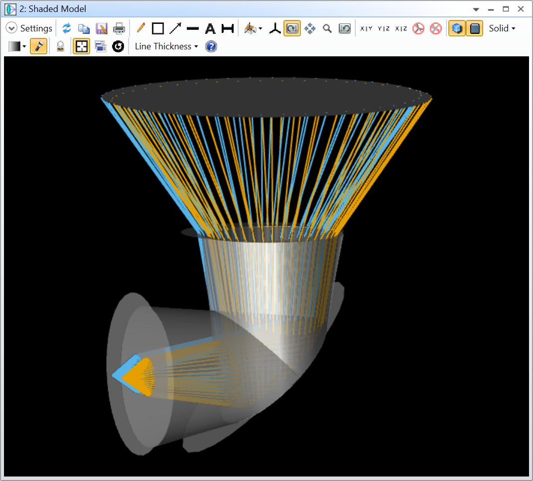
Why is the volume not created? I don’t know. But the rays are traced exactly in the same way. If you need to convince yourself, you can setup a Multi-Configuration system where one configuration doesn’t have apertures and one has apertures. Then, you can display both configurations in the same Shaded Model, and color the rays by configuration.
We only see the orange rays from the first configuration because rays from the second configuration perfectly overlays with them. You can further convince yourself by adding an X Offset to the Shaded Model to see both configurations side-by-side.
And this finally brings me to the point I wanted to address here.
Model Accuracy vs Appearance
In OpticStudio, and this is probably also true for other design/simulation softwares, there’s a distinction to be made between what a model does and how it looks like. Quite often, we have this expectation that our model should have a realistic appearance to be accurate. However, these are two different goals that are sometimes not compatible with each other. Personally, I make the most simple models for calculations and when needed, I translate those models into visually appealing ones (for presentation, rendering, or drawing).
Going back to your particular case, it seems like having a “good-looking” prism in pure sequential mode will be difficult. There are several possibilities. You could solve your design problem with a not “good-looking” but still accurate sequential prism, and then based on this model, make a non-sequential prism that you can use for rendering. That way you can perform all your sequential analyses and still have a way to display the prism should you need to. Or, you could use the mixed mode (Non-Sequential component in Sequential mode), that would allow you to model the prism in Non-Sequential and include it in a Sequential model using the Non-Sequential Component surface. This will look better visually, but there are some limitations. It all depends on what you want your model to do. Setting up a mixed-mode system can be a bit challenging at first, I recommend reading those articles:
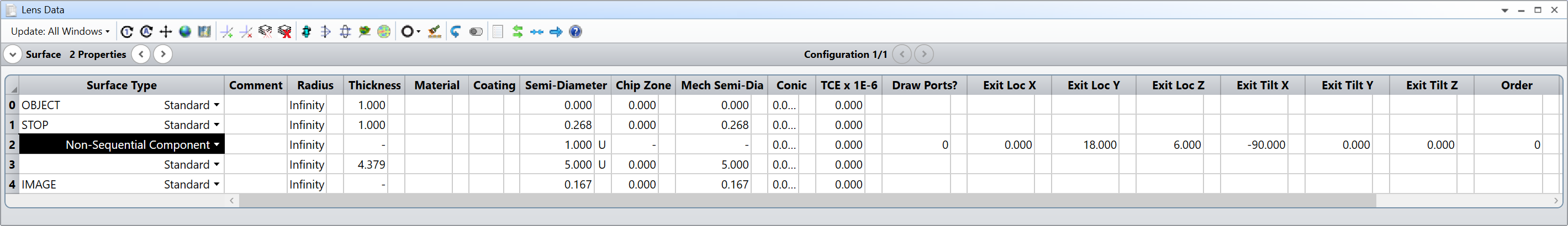
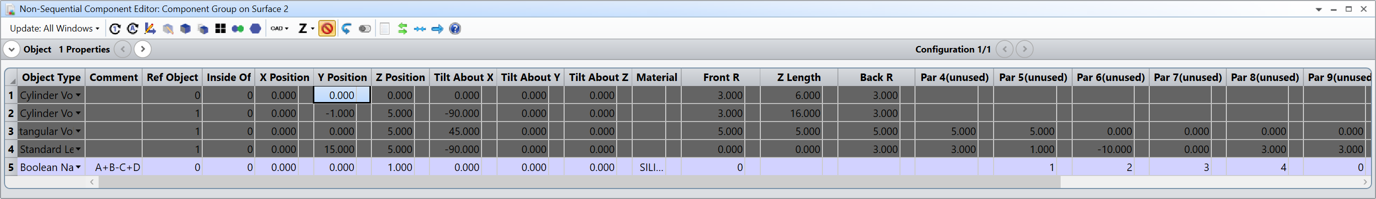
I’ve made a dummy example (see below), that I will also attach to my answer.
Notice that I’ve used a Boolean Native object to make the volume a single volume, but its again a visual trick and down the line it could slow down the ray tracing as explained in this article:
This illustrates once again that having a “good-looking” model and one that does the job is sometimes not a good idea because these endeavors compete with one another.
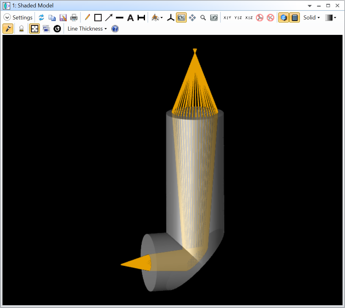
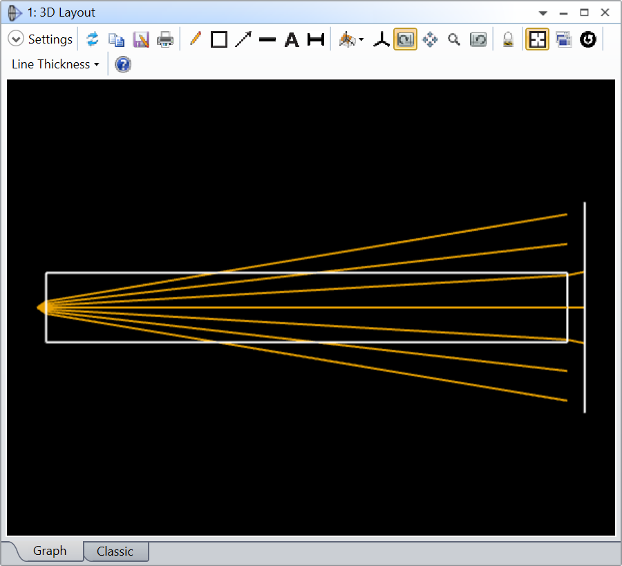
Another thing to consider is that in Sequential mode, rays must go from one surface to the next. While it might look like you have a volume, the rays will not interact with the walls of your prism. In the example below, I just have a long cylinder of SILICON.
As you can see the rays go through the cylinder walls unperturbed and they are simply terminated at the vertex of the cylinder end face. This wouldn’t be the case in Non-Sequential where some would be reflected (TIR).
This will be important for your simulation of loss. In the sequential case, the rays are terminated and will be lost. In the non-sequential case, the rays could TIR and somehow make it to the other end of the prism.
Once again, its all a matter of what you want to achieve.
Sorry for the long post, its a subject dear to my heart.
“In OpticStudio, and this is probably also true for other design/simulation softwares, there’s a distinction to be made between what a model does and how it looks like. Quite often, we have this expectation that our model should have a realistic appearance to be accurate. However, these are two different goals that are sometimes not compatible with each other.”
First off, thank you for your effort @David.Nguyen. I very much enjoyed reading the context you provided. It helped me a lot to understand this software as I was beginning to grow unsure of its capabilities.
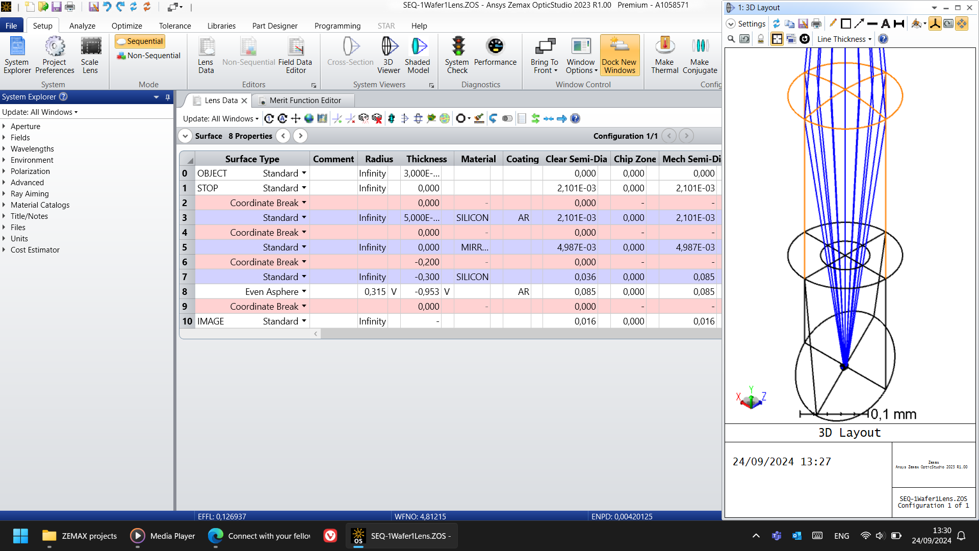
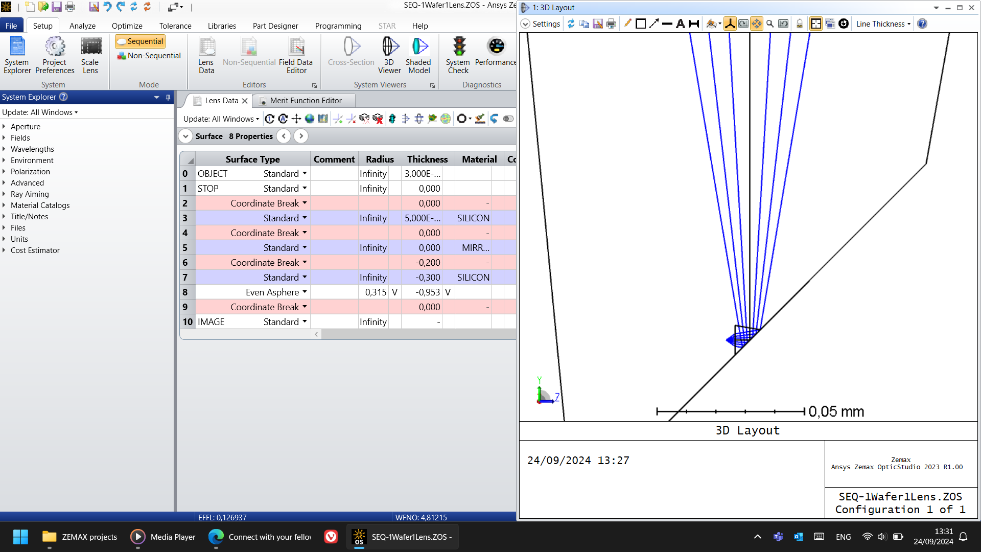
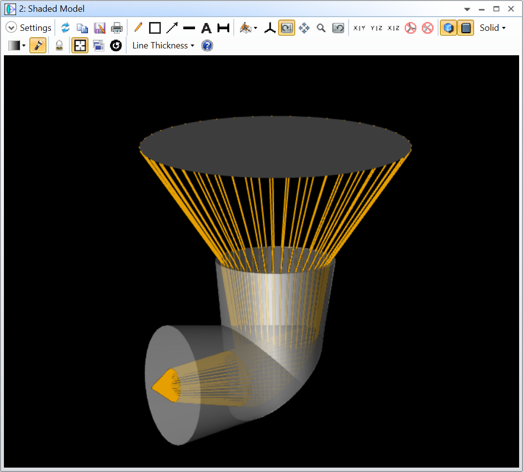
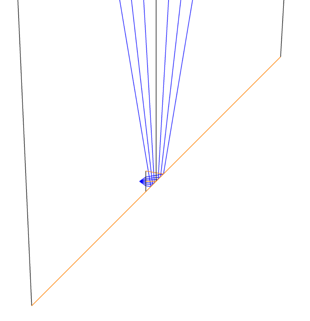
Indeed its visual representation doesn’t match its simulation. My prism, based on the 3D sketch is inside my lens. But if I make the mirror aperture rectangular, it then corrects itself, visually. But you could always see that the rays were refracting as expected. All of this added to a lot of confusion, for sure.
With no aperture:
With rectangular aperture:
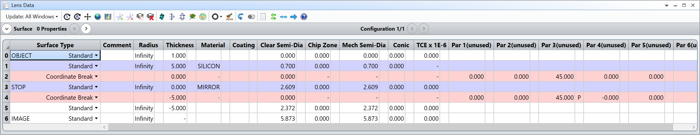
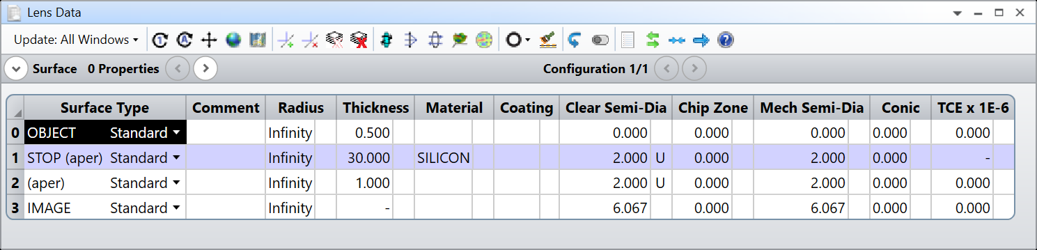
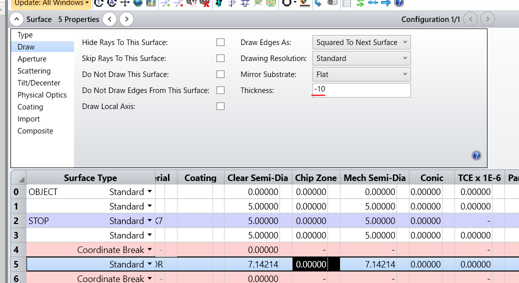
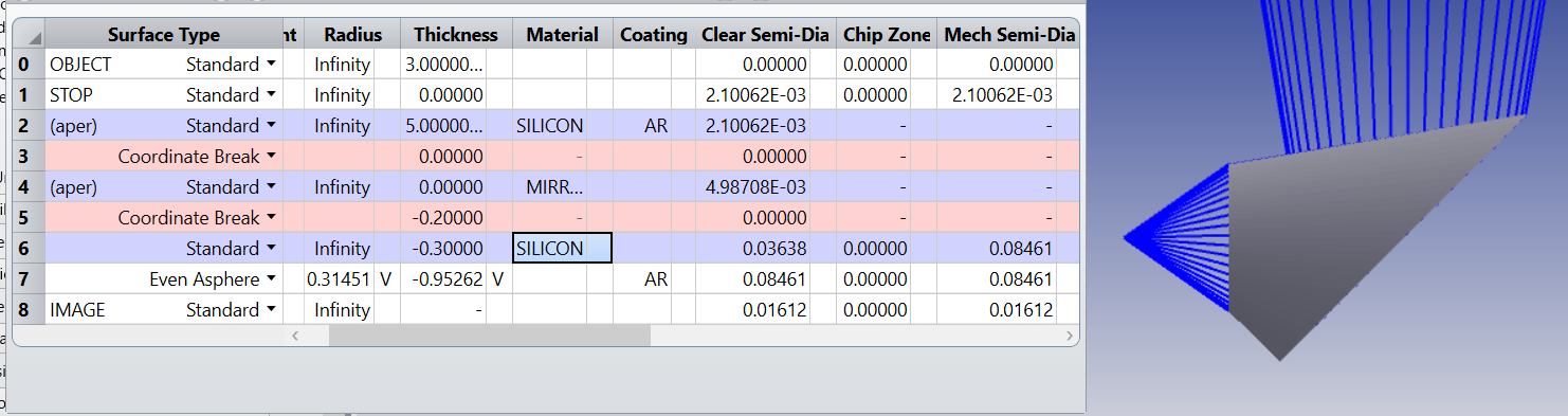
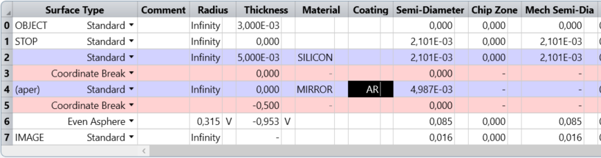
So, considering how a mirror selects its material, I then don’t need another surface in front of it. I create a first silicon entrance one, a coordinate break, the mirror, and on the second coordinate break, I just make it much thicker and that’s it. No need for another surface after it. Just like you show on that first picture of yours with the Lens Data.
My example:
My issue is that the energy transmitted to my receptor does not match the expected calculations. When using unpolarized light, and considering polarization in the Physical Optics Propagation, I get a total power of 41% when it should be 49%, according to normal incidence (Fresnel equations - Wikipedia). But if I add an AR coating to the MIRROR surface, the expected power matches.
Why is that? What sense does it make to add a coating to a MIRROR surface? Shouldn't it be a continuous solid that reflects all light, as per the manual? What am I not understanding here about how MIRRORS work in this software?
I must say I'm trained in microelectronics, and not in the physics of light. So many of these notions get lost on me and need constant revision.
Like any other software, OpticStudio isn’t perfect, but as far as I’ve been using it, I’d say you can thrust in its capacity. I’ve had bugs and crashes, but the physics was always right. Its good to keep questioning what the software is doing, and also its good to understand its limitations, so you know in what boundaries you are working.
MIRROR isn’t a perfectly reflective surface. If you read the Help File section I refereed to above (Conventions and Definitions » Glasses), you’ll find that:
If a surface or object has the material type MIRROR, light will only be reflected. The transmitted part will be ignored. The behavior is different depending on whether a coating has been specified:
If no coating is specified, the surface is assumed to be coated with a thick layer of aluminum, with an index of refraction 0.7 - 7.0i. The aluminum layer is assumed to be thick enough that no light propagates past the layer. This means that an uncoated mirror surface has a reflectivity of less than 1 although the exact value will depend on the polarization of the rays.
If a coating is specified, the reflectivity will be that of the coating.
If you need a perfectly reflective surface, you could use an IDEAL coating. There’s one already in the default catalog of OpticStudio called REFLECT and is defined as such:
Well, thank you again. This has been humbling. My lack of knowledge into the physics of light leads into frustration, which causes issues. I must have read somewhere these mirrors were perfect, but even as I read that description in the manual, I didn't pay attention to it and just assumed the transmission value was super close to 0. A sort of reading without looking.
All of this is still overwhelming for me, as I navigate it.
I created a coating as you mentioned, with perfect reflection and the values are much closer to expected, according to some simple calculations.
It seems I take from this "less, but better". I tried to add too many elements to the simulation.
I did the same mistakes than you. And for your defense, it isn’t really obvious that MIRROR should be aluminum.
While these aspects can be frustrating at times, remember that this is a journey, and today you’ve learned new things about OpticStudio and its something to celebrate 😀