Solved

How to define my interest of source file as a Source Object

  • 17 January 2022
  • 13 replies
  • 578 views

Userlevel 1

I have a light source (LED)in my hand with spectral graph, I would like to analyze its spectral distributions in studio. In knowledge base LED modelling is there. But this is not as direct as adding the coating files in catalogue. Help me to fix this.

icon

Best answer by David.Nguyen 18 January 2022, 14:58

View original

13 replies

Userlevel 7
Badge +2

Hi Ebi,


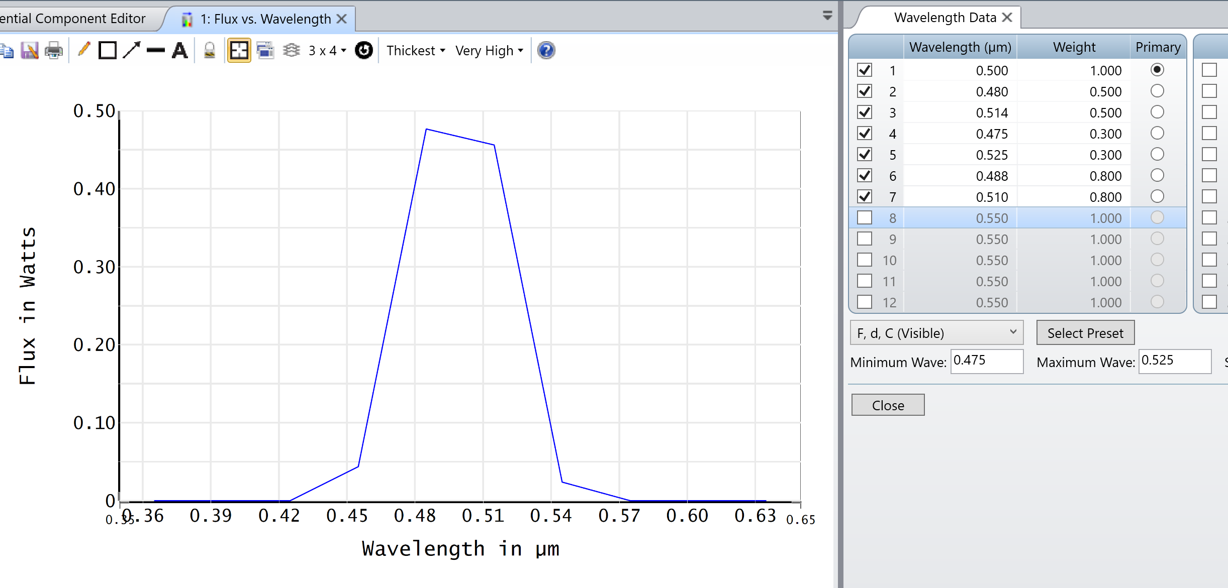
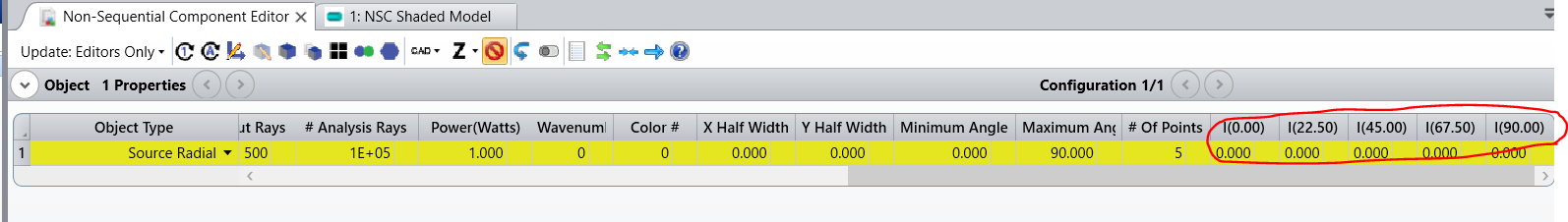
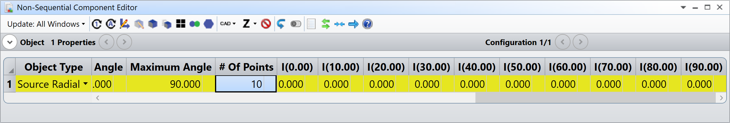
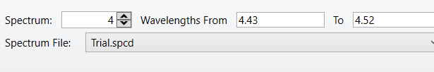
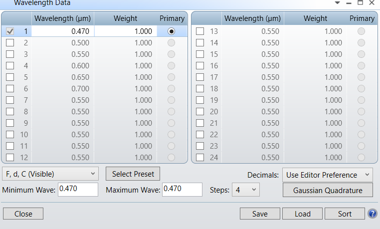
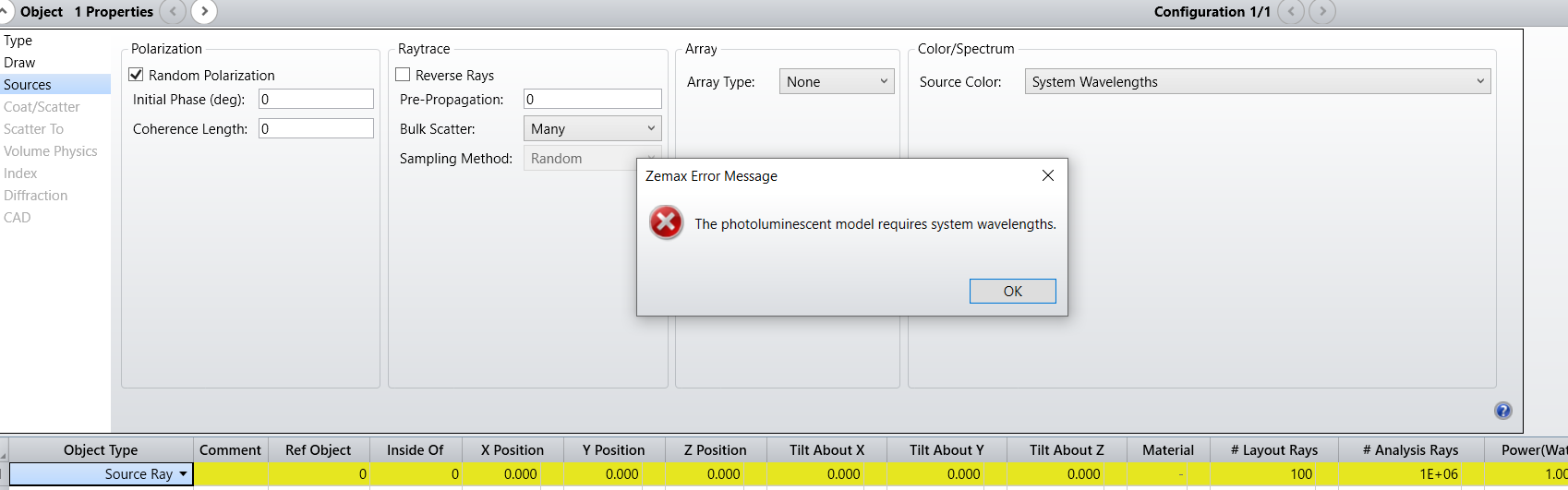
Could you give us more information about what you are trying to achieve and what data you have at hand? If you want to have a quick first approximation, you can setup your wavelengths in Setup..System Explorer..Wavelengths. There, if you double-click on Wavelengths it’ll open the Wavelength Data Editor. In this editor, you can then specify a couple of wavelengths and their associated weight. Then, your source will launch rays based on the wavelengths that are defined in the editor, and the amount of energy is scaled with the associated weight if this makes sense. Make sure you double-click on your source in the non-sequential data editor to open its properties, and go to Source and on the right of the window select System Wavelengths as the Source Color.

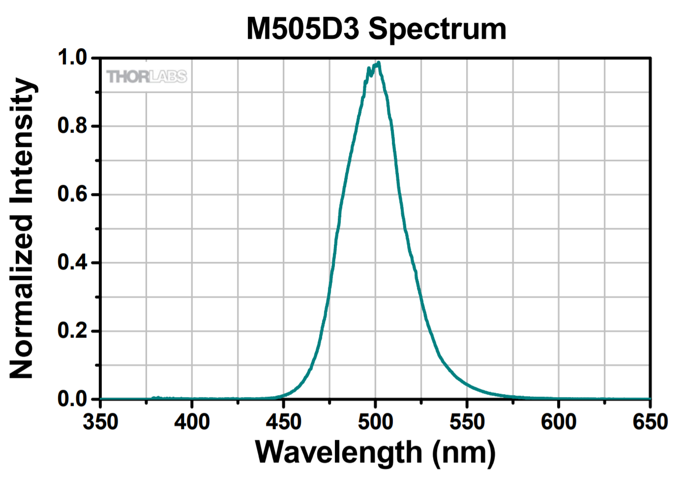
I have made a simlpe example for you based on THORLABS M505D3 (I eyeballed the plot values, but if you ask your manufacturer they usually give it to you):

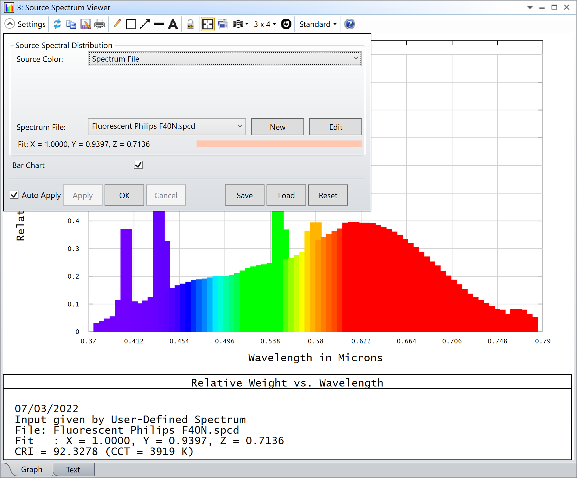
This is what it looks like with the Analyze..Flux vs. Wavelength tool (with smoothing):

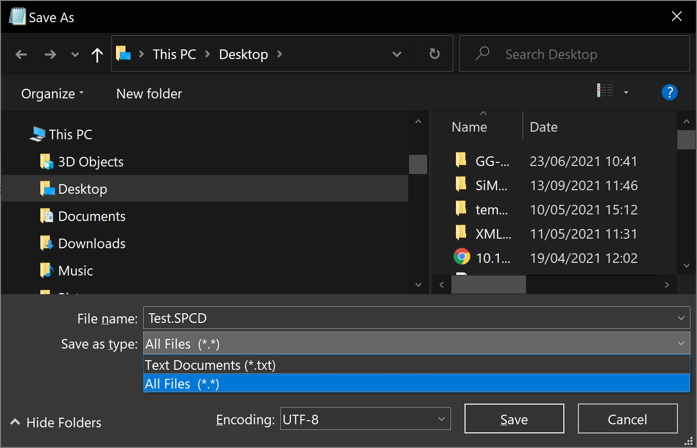
Definitely not perfect, but it gives you a quick first approximation. If you want to get something more elaborate, I’d suggest making your own spectrum file. It is basically a text file containing all the wavelengths and their weights. The syntax can be found in the Help File (F1) under The Setup Tab > Editors Group (Setup Tab) > Non-sequential Component Editor > Object Properties (non-sequential component editor) > Sources > Defining a spectrum file. For your reference, it reads:


Spectrum files are in text format, end in the extension *.SPCD, and are placed in the <objects>\Sources\Spectrum Files folder (see “Folders”). The files are used to describe a user-defined spectrum for source color modeling. The file format is pairs of numbers in the following format:

# comment <optional>
wavelength1 weight1
wavelength2 weight2
etc...The wavelength values are in micrometers and must be listed in ascending order. The weight values are in dimensionless relative power units. At least 3 but no more than 200 pairs of data points may be defined.


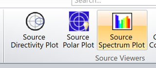
Once you have the file ready and located correctly, just go back to your source properties, and change the Source Color for Spectrum File and select your file.

Let me know if that makes sense, and take care,


David

Userlevel 1

Thank you so much David sir, Enlightened!:sunglasses:


Am really happy and excited about How Zemax forum helps the beginners like me. Its Amazing. Thank You ZEMAX for making such platform for Active Communication.

Userlevel 1
Variable Angular data in Source Radial

Here it allows only particular angular data to be added, I want to add more angular data like I(5),I(10),I(15)……. Kindly guide me on how to achieve this?


Sorry I forget to reply your question. I have I vs Wavelength data and Spatial distribution(Angular data) data. Is this adequate to simulate my LED or any other parameters I should add, I mean LED diameter etc… And which Source type is best suitable for LED ? 


Thanks and Reg 

EBI

Userlevel 7
Badge +2

Dear Ebi,


In your screenshot, on the left of the red-contoured columns, there’s a parameter called # Of Points for the Source Radial. By changing this number, you will increase the number of points available to you. Below is an example with 10 points:

Let me know if that makes sense.

The Source Radial is also a good starting point for modelling your LED. As you noted however, it is a point source, and doesn’t have a spatial distribution. The question whether, which LED model is best suited really depends on your application and what you are trying to achieve. In general, I would recommend to start with a simple model, like the Source Radial, and increase in complexity as you feel there is a need for it. For example, by introducing the spatial distribution. Also, note that in some instances (I’m thinking about OSRAM for example), your LED manufacturer can have ray files that they generated for their LEDs, which they share with their customers (have a look at this article for more details).

Take care,


David

Userlevel 1

Dear David sir, 


Thanks for the time and help. I will go through the article.

Ebi


Userlevel 1

Dear David , 

Thank you so much, its amazing. One more thing, I have tried to convert the text into SPCD .ext. But it seems unable to do with notepad. Kindly help me how to convert SPCD.


Userlevel 7
Badge +2

Hi Ebi,


Could you share the text you are trying to convert to *.SPCD?

In Notepad, when you save your text file, you need to change the Save as type drop-down menu to All Files (*.*).

Is that what you were doing? Otherwise, and this is a problem if you hide known file extensions in Windows, it might have created a file <file_name>.SPCD.TXT.

Hope this helps, and take care,


David

Userlevel 1

Thanks dear David. I made it. But how can I be sure that the wavelengths are inserted. Any possible way to confirm the wavelengths by detectors or any tools except the tab showing above the spectrum file in the below screenshot


Regards

Ebi


Userlevel 7
Badge +2

Hi Ebi,


The analysis you want can be found under Libraries..Source Spectrum Plot.


Change the settings to Source Color: Spectrum File and select your spectrum file from the drop-down menu.


I hope this helps.

Take care,


David


Userlevel 1

Hi Dear David, Thanks for the help.

when I am using spectrum file it works well, but not in every case, for example in Photoluminescence it shows system wavelength can only be used . Why ?  How can we use the spectrum file in such case. Or any other possible way to define the source with more than  24 wavelengths in system wavelength ?


​​​


Userlevel 7
Badge +2

Hi Ebi,


I’m not quite sure how you get that error message. Could you share a simple example that demonstrates the issue?

I know some people use the Multi-Configuration Editor with the WAVE operand to specify more than 24 wavelengths some times, but it really depends on the kind of analysis you’d like to do, most analysis won’t support this trick.

Take care,


David


Userlevel 1

Hi Dear David, 


Let me share the article on Photoluminescence. I have used the spectrum file as source here. It shows error. If there is no way of using spcd here, can you please guide me on using more than 30 wavelength in system wave


Ebi

Userlevel 1

Hi Dear David, 

Split unchecked
Split checked (Unwanted reflection from lens)

I modelled lens (obj-1) and Beam Splitter (Obj-2), When the light pass through lens, it shows transmitted light along with reflection backward (Fresnel!).  Reflection  is visible whenever the split rays in object property is checked. I don't want the layout to show such reflection on lens, so I unchecked split rays. but this affects my next object (Beam splitter) from being reflective.  Though I have used COAT I.99 for lens surfaces to prevent reflection, it didn't seem working. (The lens are I.99 Coated - shown in image) Kindly suggest ways to solve this.

Thanks

Ebi


Reply