Solved

Grid Gradient as step-index fiber with FICL

  • 7 May 2021
  • 1 reply
  • 353 views

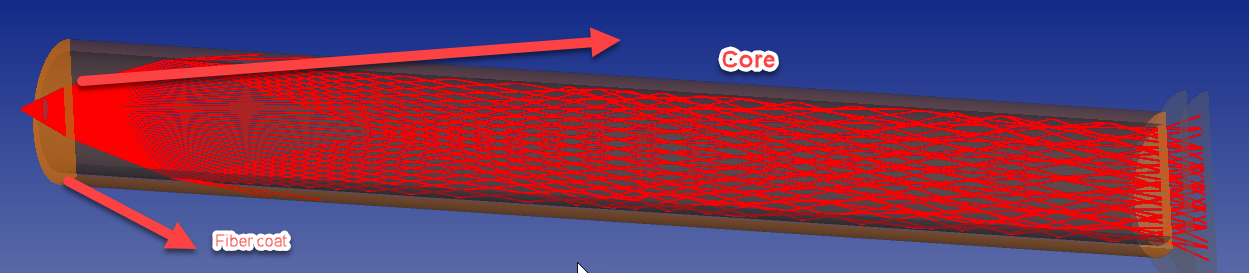
I'd like to model a step-index optical fiber (because I'm interested in modyfing it).

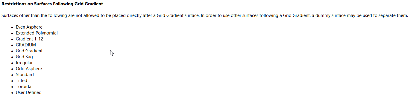
I tried to do that with a Grid Gradient with 1.55 - core index, 1.45 coat index, 4.6 um - core radius, 0.1 um - \Delta t

I created a Universal Plot with x - distance from the fiber face to the IMAGE surface, and y - FICL.

The problem is, the plot is almost identical with the fiber modeled as a Standard surface with 1.55 index, and both models change the FICL plot drastically when length of the fiber is changed.

I need to model fiber in such way, that changing length won't change simulation results.


1. Is it good idea to model step-index as Grid Gradient, or is there simpler way to do that?

2. Is FICL good enough to recognize the way light propagates through optical fiber or should I go for POP?


Also, I'd like to modify the fiber, firstly, by milling a lens in its face. I went for Standard surface with some radius. There are two problems:


3. The lens is created on top of the fiber face. Is there any simple way, to put it inside fiber?

4. Clear semi-diameter defines size of the lens, but it also blocks light propagating through no-lens surface. I'd like to simulate diffraction on the edge of the lens. Is there any simple way to that?


Below is a rough sketch of my model
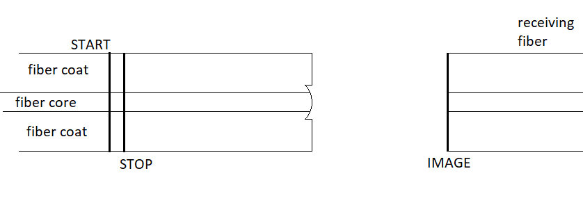

Thanks in advance.

icon

Best answer by Sahil 26 May 2021, 17:20

View original

1 reply

Userlevel 4
Badge +1

Hello Konard ,


1st Answer : - 


As for step index either for multi mode or single mode . As Grid Gradient is a flat circular surface with an index of refraction defined for a grid of coordinates in three dimensions . Grid Gradient has some restrictions . 


As seen from your rough sketch I will suggest to follow Mixed Mode . You can have Non sequential components Cyclinder Volume outer 1.45 coat index (FK3 in Zemax Material catalog with index 1.46 ) and Core index 1.55 (K5 in Zemax Material catalog with index 1.52 ) or you can select based on your requirements . You can refer this simulation file  (Core clad fiber.zmx) :  'C:\Users\YourName\OneDrive - Zemax LLC\Documents\Zemax\Samples\Non-sequential\Fibers\Core clad fiber.zmx'


2nd Answer : -


The answer based on your requirement . If the source diode has large divergence better to use FICL and if its less then better to go for POP. In POP diffraction is considered in from starting point to end whereas IN FICL it will consider diffraction in the end of fiber. But again POP has limitations. If your optical setup has Mixed Mode such as example I have refer you then POP will be applied only on Non Sequential parts.


Please visit this forum post for more information : Should I use POP or Single Mode Coupling for my single-mode fiber coupling system?


Should I use POP or Single Mode Coupling for my single-mode fiber coupling system? 


Limitations of POP in NSC in Help file :


The Analyze Tab (sequential ui mode) > Laser and Fibers Group > About Physical Optics Propagation > Propagating Through Non-sequential Surface


3rd Answer : 


This I have to look inside the Knowledgebase or cases . This is good question . I will find and update the answer later in this forum post. May be you are talking about lensed Fiber ? 


4th Answer : -


This can be done in POP . As POP consider all diffraction effects from start to end . This is forum post Link I would like to refer simulating for both POP and FICL both. Please visit knowledgebase 


Single-mode fiber coupling in OpticStudio 


How to model multi-mode fiber coupling 


Regards


Sahil


Reply