For a set of collimating lens that I designed I got good enough MTF but the image is out of focus:
- What can be the reason for this phenomenon?
-Furthermore, changing the refractive index from “fixed” to “mode” casue a degradation of the mtf!
what happend here?
Thanks,
Nadav
Best answer by Angel Morales
Hi Nadav,
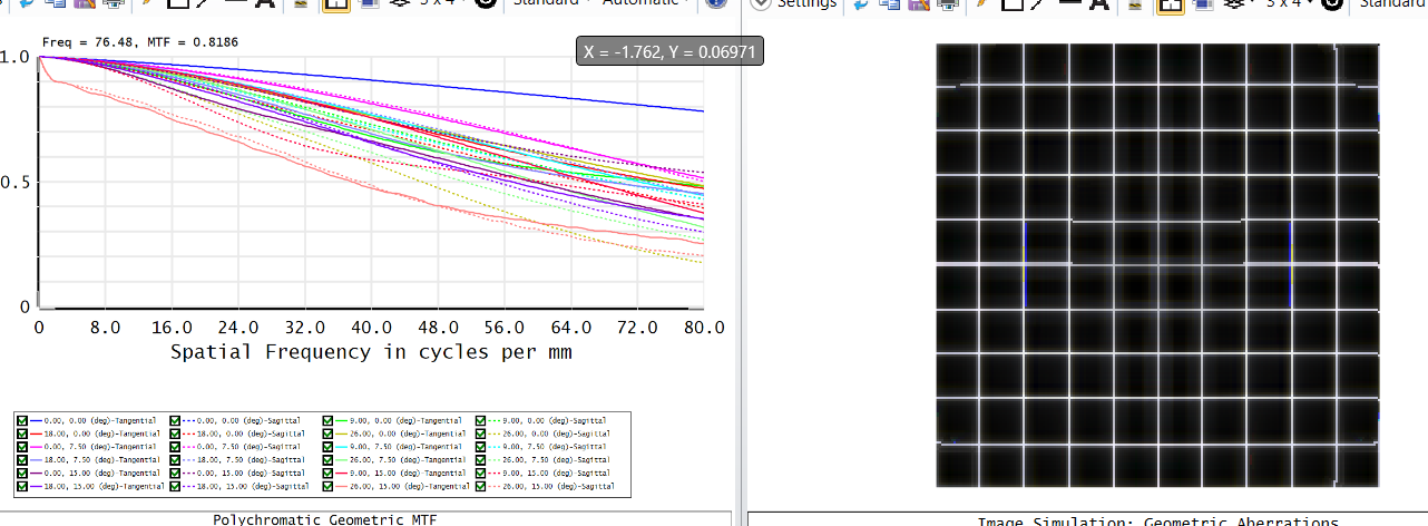
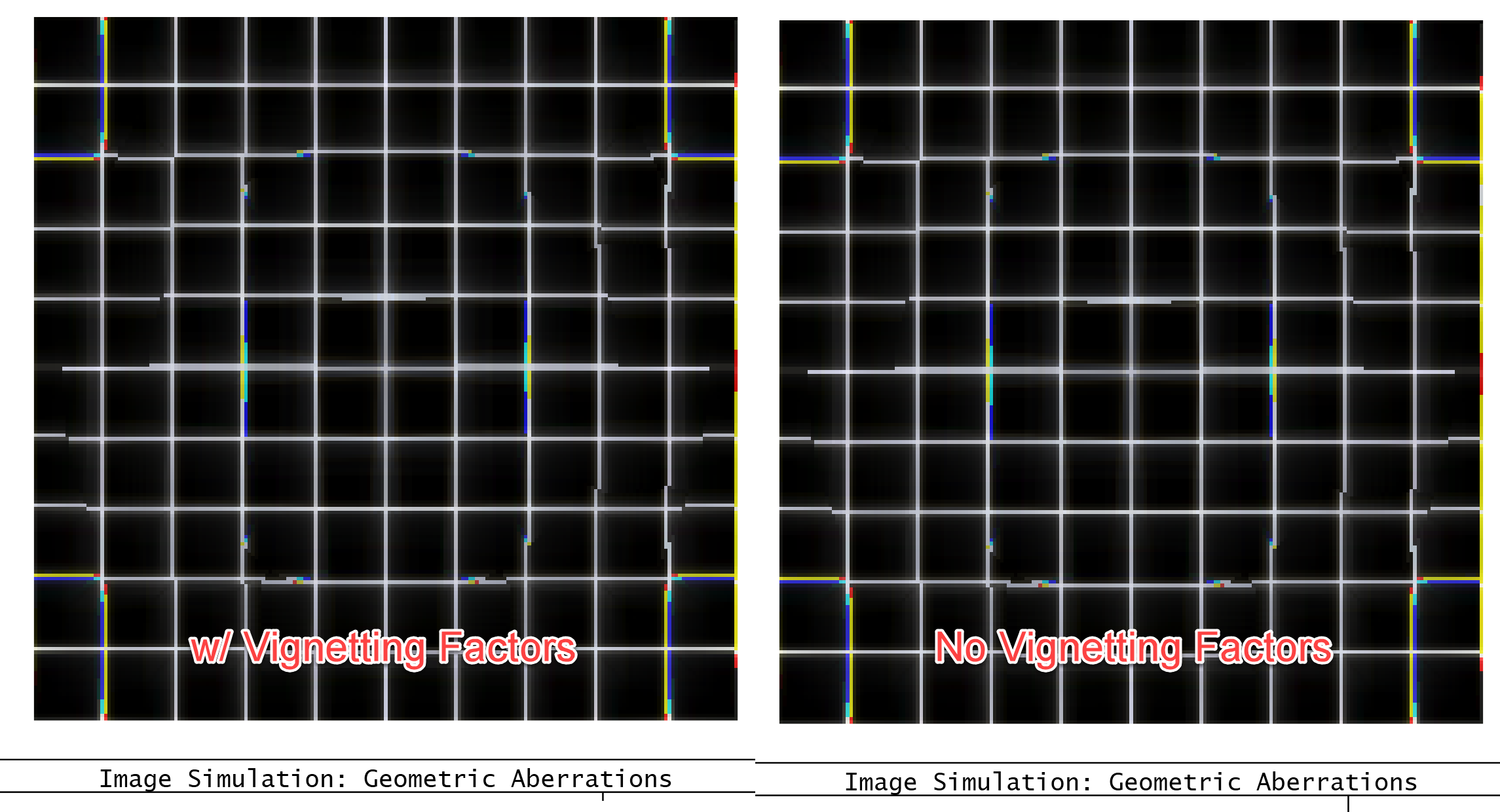
Thanks for your follow-ups here. I’ve taken a closer look at your provided system, and it looks like the difference between your Image Simulation results and your expected simulation comes down to the use of vignetting factors.
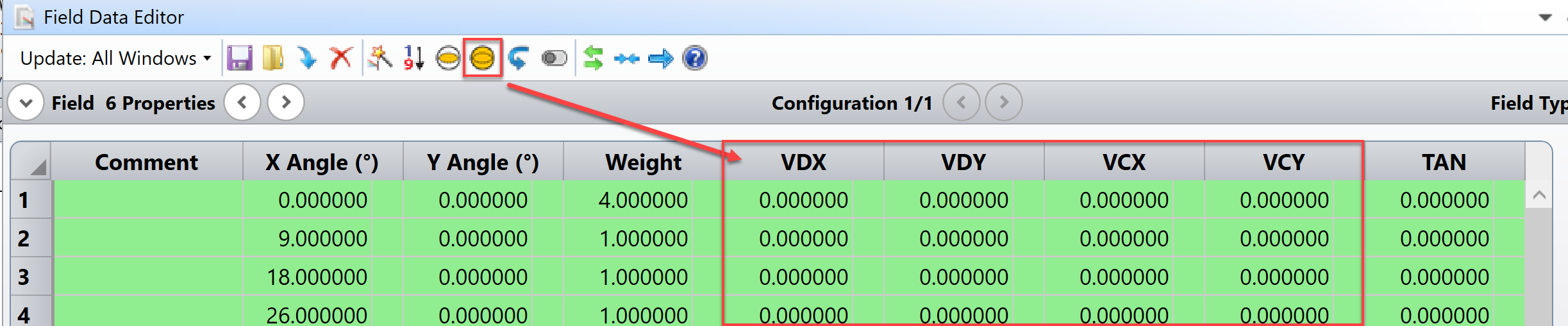
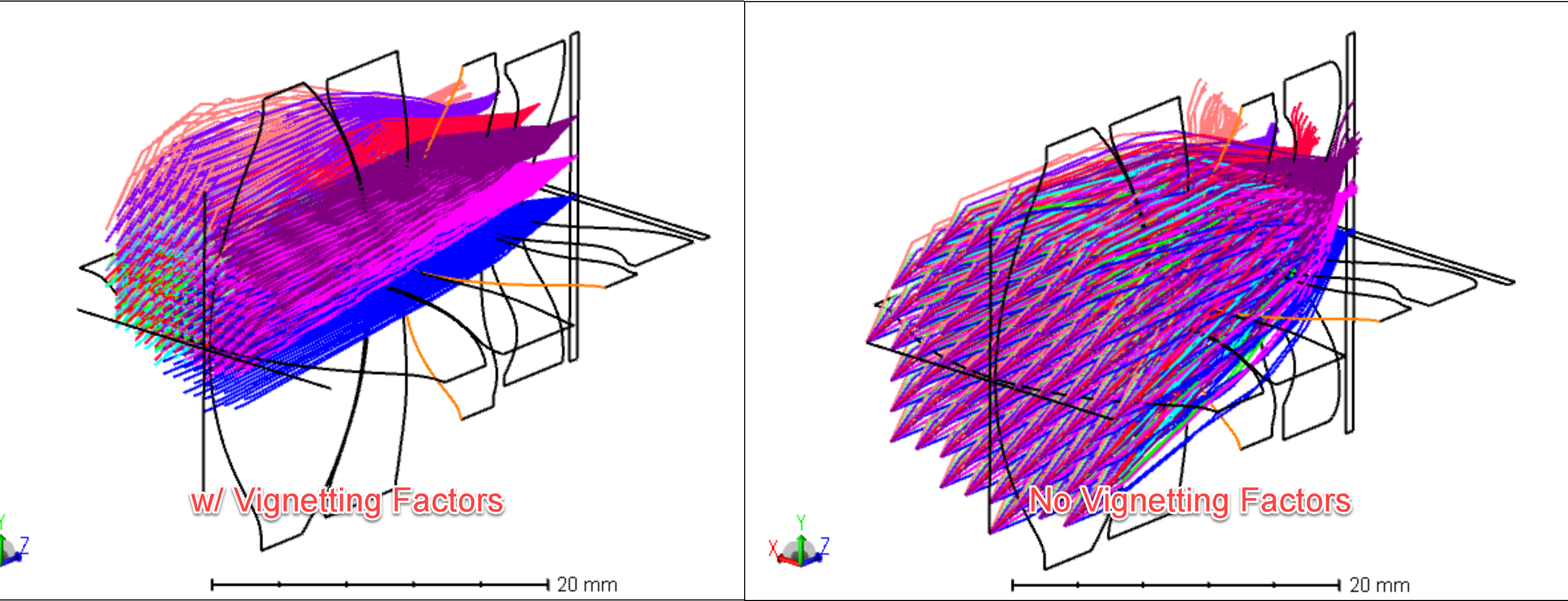
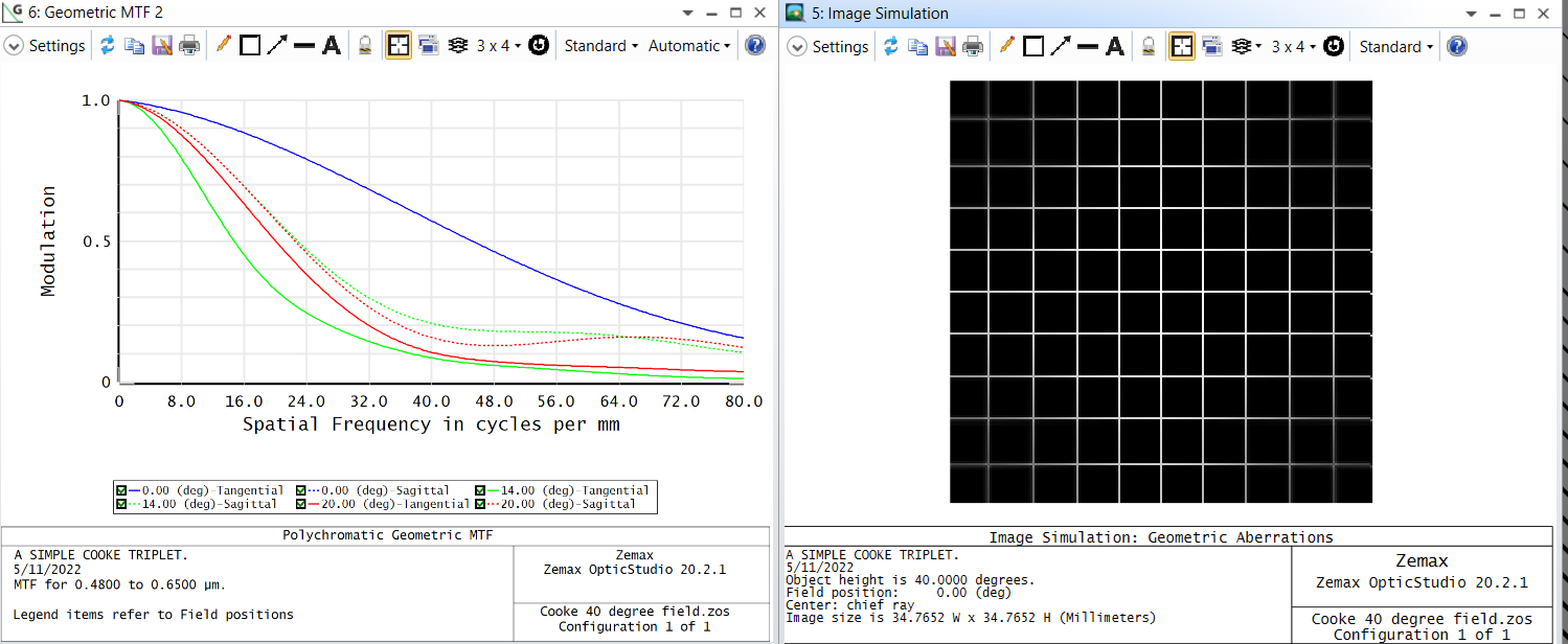
I noticed that you had defined vignetting factors for all field points in your Field Data Editor. Some, but not all, analyses will take these factors into account. I noticed that when I removed the vignetting factors from your model (using the Remove Vignetting Factors function in the FDE toolbar), results like the Geometric MTF and Spot Size change, but the Image Simulation result does not:
I’d need to double-check if this is intentional or not, but it’s clear that Image Simulation doesn’t take into account the vignetting factors. It’s possible there is difficulty to take into account vignetting factors to generate a PSF Grid which may have many field points not explicitly defined with vignetting factors.
In any case, I do think it’s overall a tricky situation, as your vignetting factors were defining some input light that was very specific to each field point (almost like a shifting input beam per field point), rather than having the factors mimic some clipping that would be imparted by apertures. So, I do not think there is a way to define some physical apertures that would clip rays to achieve the input rays you’re currently modeling.
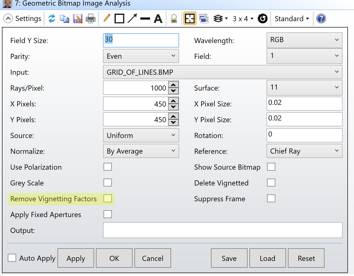
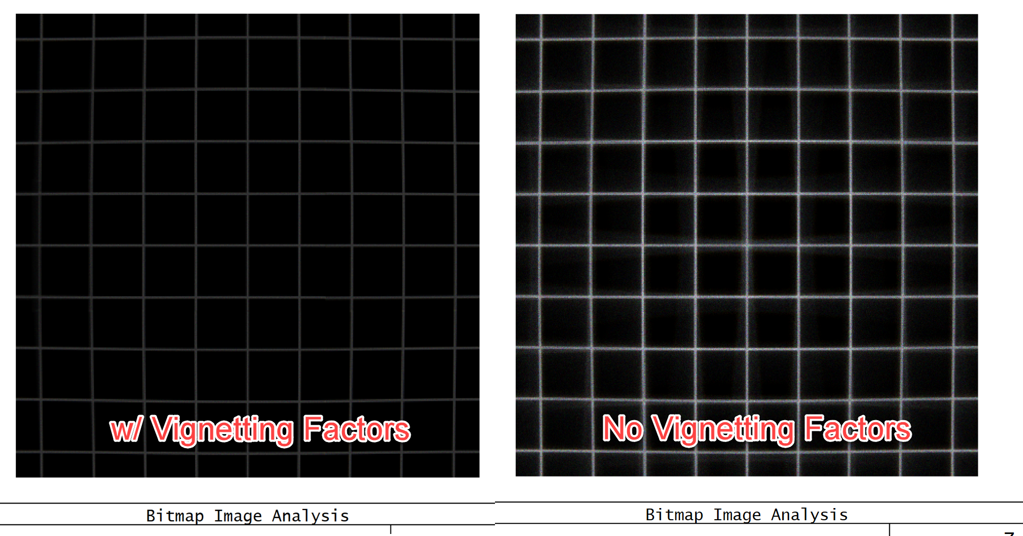
That said, you might want to instead turn to an analysis like Geometric Bitmap Image Analysis. This is strictly ray-based (rather than a convolution of a PSF Grid with your input image), and there is a setting where you can opt to retain your vignetting factors:
Let us know how these thoughts work out for you or if you have any more questions here. Thanks again for your time, and I hope you have an excellent rest of your day ahead!
It’s going to be tricky to give a definitive answer here because the attached file doesn’t have all the information needed. There’s a material catalog you are using that doesn’t go through in a .zos file, so when I opened up your system I didn’t see it quite as it is. I also don’t know what settings you are using for the Image Simulation tool. They can change the output quite a lot. The solution to this is to make an archive .zar file for your attachment (inside a .zip file still) so that all the settings and other files needed will come through.
For the model glass, the likely answer is that a model glass is not an exact match to a fixed glass. Model glasses use three quantities to describe the index, while fixed glasses use more and provide a more exact representation of the behavior. While the difference is frequently minor, it can affect the analysis, such as with an MTF.
If you’d like to re-send a .zar file, or open up a case with us, we can try to say more on this.
Thanks for resolving the material issue. I’m afraid I still can’t see the effect that you are seeing or that is in your screen shot. The problem is that with a .zos file, I don’t have the settings you are using in other tools, mainly the Image Simulation. When I open your file here, I still have the settings that are saved on my computer, and the simulated image looks fine. I need the full configuration to match your system. My previous answer with the model glass may be the reason for your image, but it may well also be your choice of settings in the IS tool. I’ll have to know more before I can come up with a more definitive answer.
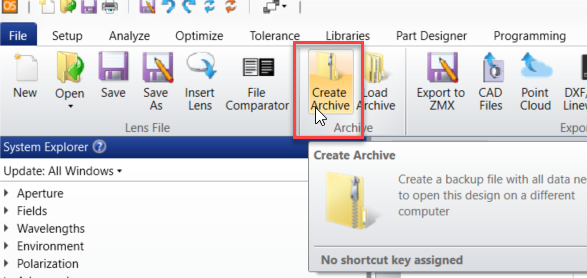
The solution is an archive file, which is a .zar extension rather than the .zos. It’s easy to make one. Just go to the File tab and click the Create Archive button and follow the prompts, which are mostly just going to be clicking Okay at a couple of prompts. Like this:
Then you can send the .zar file (inside a .zip file) and all of the analyses will run correctly.
I took at look at the last file. I think you’ve changed a few things because I’m not seeing exactly what you have in the screenshot up above, but it is showing the qualitative behavior of having a fuzzy middle section. I think this is simply how your system is corrected. If you go to the settings you can display the PSF grid, and indeed the central point spread function is broader than the surrounding ones, indicating that the central region will be less corrected. I don’t know where the design came from and there’s no merit function, but what we’re seeing is consistent with the PSFs the system creates.
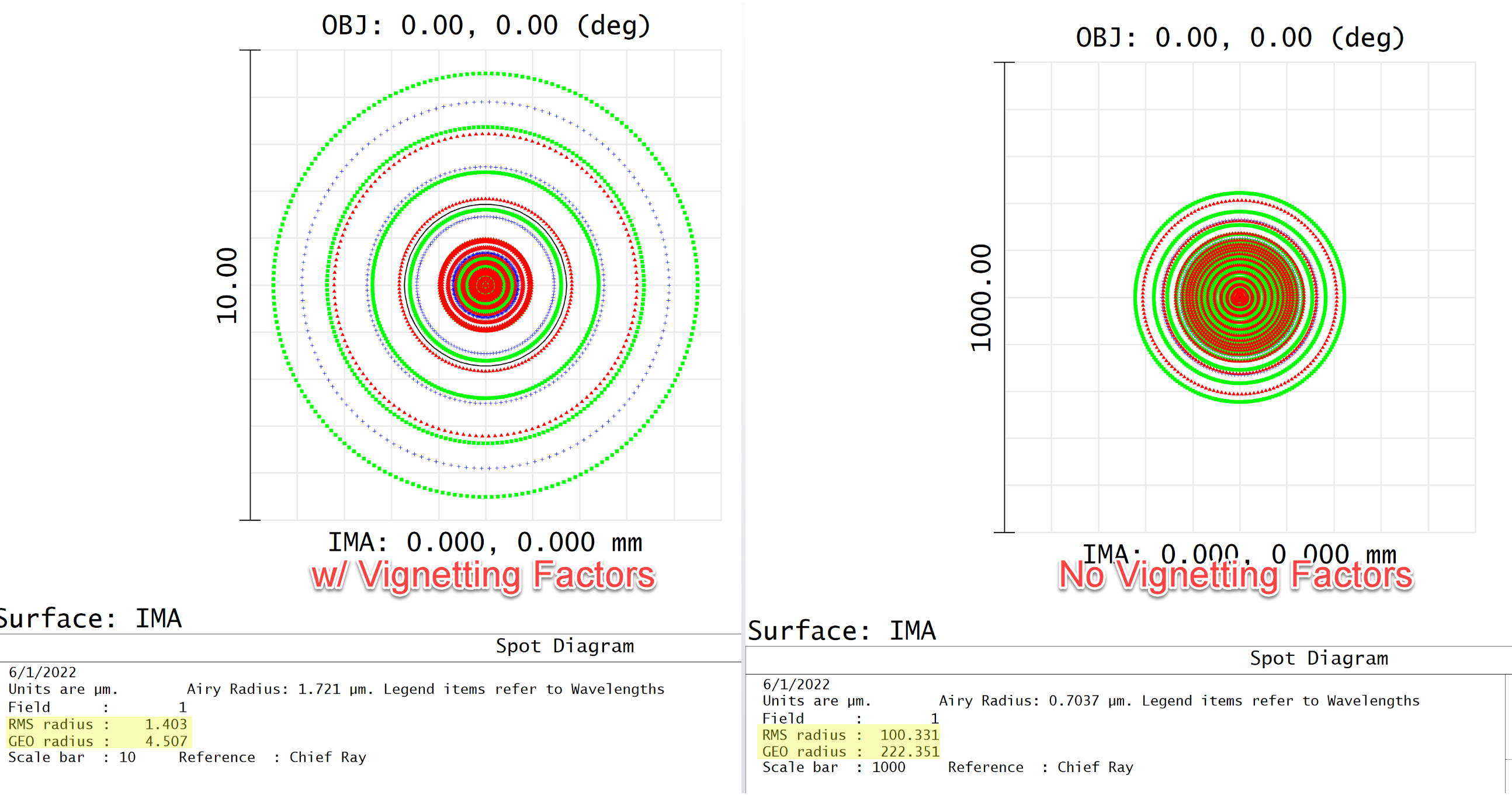
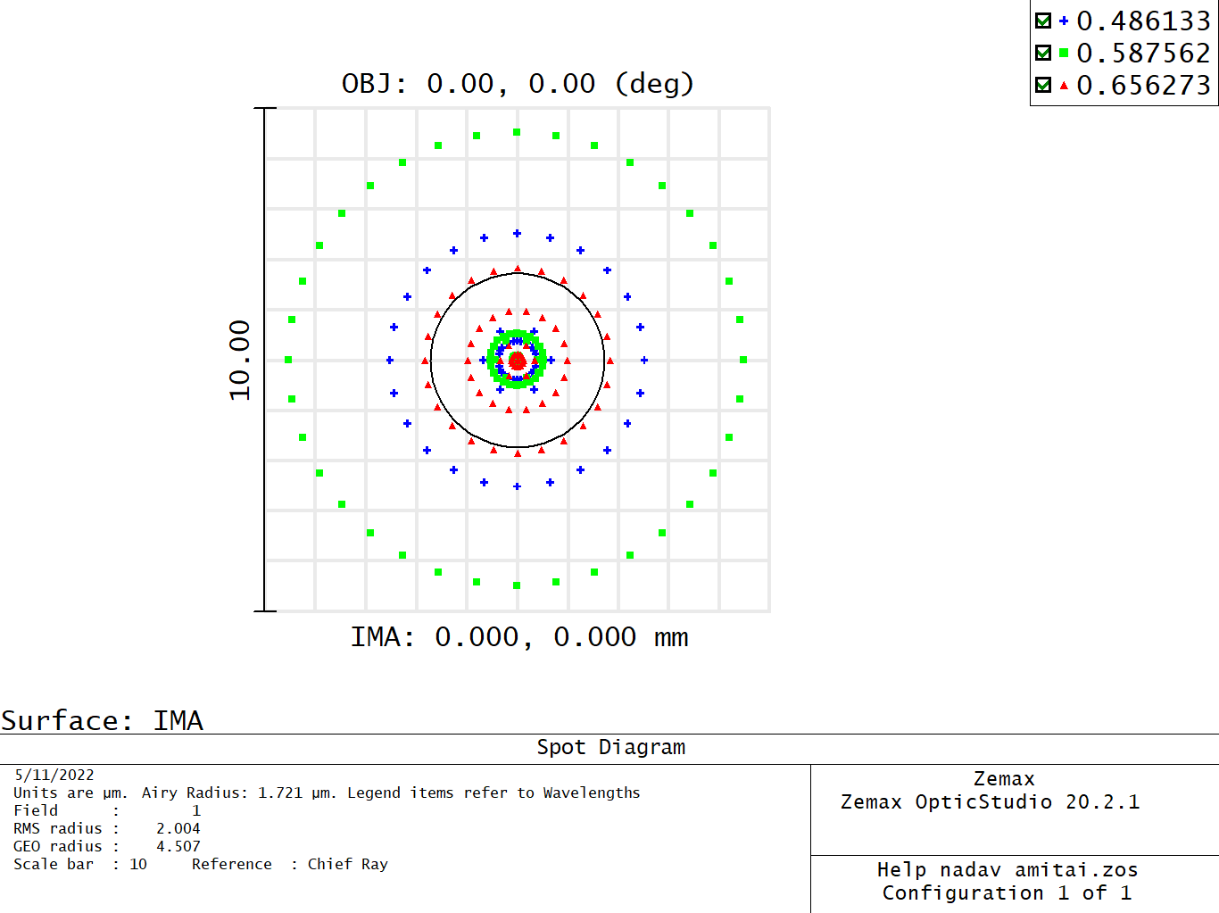
For the MTF changes with material, I do think you are seeing the result of a change in the glass properties. Small changes in a focused system can produce large degradations. You can see this even in tools like a spot diagram, where the RMS increases four times just by replacing the actual glasses with model glasses.
Thanks for your follow-ups here. I’ve taken a closer look at your provided system, and it looks like the difference between your Image Simulation results and your expected simulation comes down to the use of vignetting factors.
I noticed that you had defined vignetting factors for all field points in your Field Data Editor. Some, but not all, analyses will take these factors into account. I noticed that when I removed the vignetting factors from your model (using the Remove Vignetting Factors function in the FDE toolbar), results like the Geometric MTF and Spot Size change, but the Image Simulation result does not:
I’d need to double-check if this is intentional or not, but it’s clear that Image Simulation doesn’t take into account the vignetting factors. It’s possible there is difficulty to take into account vignetting factors to generate a PSF Grid which may have many field points not explicitly defined with vignetting factors.
In any case, I do think it’s overall a tricky situation, as your vignetting factors were defining some input light that was very specific to each field point (almost like a shifting input beam per field point), rather than having the factors mimic some clipping that would be imparted by apertures. So, I do not think there is a way to define some physical apertures that would clip rays to achieve the input rays you’re currently modeling.
That said, you might want to instead turn to an analysis like Geometric Bitmap Image Analysis. This is strictly ray-based (rather than a convolution of a PSF Grid with your input image), and there is a setting where you can opt to retain your vignetting factors:
Let us know how these thoughts work out for you or if you have any more questions here. Thanks again for your time, and I hope you have an excellent rest of your day ahead!
We use 3 different kinds of cookies. You can choose which cookies you want to accept. We need basic cookies to make this site work, therefore these are the minimum you can select. Learn more about our cookies.