Hello,

I have the following question:
I have a spherical curved refracting surface with n=2 and a gaussian beam with distance d between beam waist and the point where the beam hits this surface. I am analyzing the beam parameters z0 (=waist location) and w0 (=waist diameter) after the refraction (GBSP, GBSW). This works fine and the results follow my theory.
Then I implemented a vertical decenter of the refracting surface. This also works fine. The results look okay.
When I implement a surface tilt instead of the surface decenter...also everything works fine.
Then I tried the following:
I first implemented a surface decenter with a coordinate break 1 and then a surface tilt with another coordinate break 2. And now I get results that make me doubt…

Then I made the following: I compared the results of 2 scenarios:
Scenario A: tilt 1, decenter 1.
Scenario B: tilt 2, decenter 2.

I have choosen tilt 2 and decenter 2 in a way that in both cases A and B angle of incidence (RAID) and distance d (RAGZ) are the same. Because it is a spherical surface I would assume that Zemax provides in both cases the same beam results for the refracted beam. But this is not the case.

Can someone help to clearify this?

Thanks in advance and best regards

Dirk


Hi Dirk,

Thanks for your post here!

To be honest, it’s a bit tough to diagnose what could be the issue without knowing some specific details about the decenters/tilts you’re using. Are the Coordinate Break surfaces co-located and imparting tilts/decenters that are not in the same direction, but still giving you identical RAID and RAGZ values? Are the Coordinate Breaks in different spatial positions?

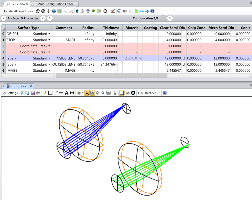
For the second situation, I think we’d need to see your file first-hand to investigate further. I did try to define orthogonal tilts/decenters in two different configurations (one has decenter/tilt w.r.t. the X axis, the other Y):


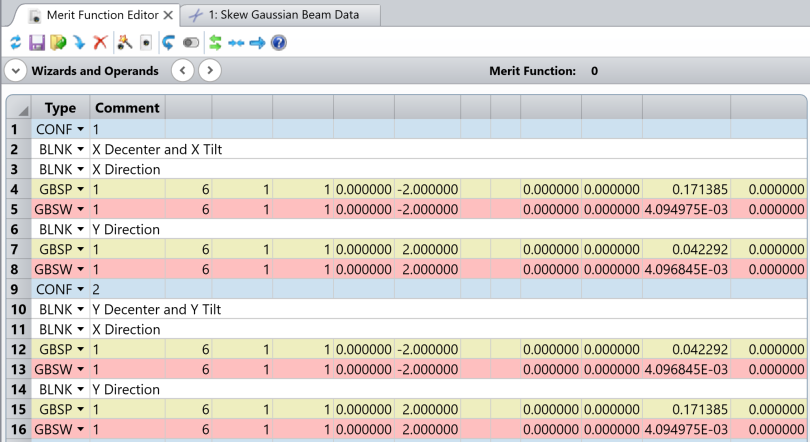
Here, I see that the GBSP and GBSW values are retained in each configuration, though I did need to use the -W0 value to obtain X-direction results:


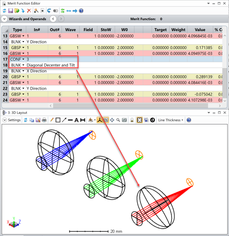
I did also try a third configuration where I imparted the same tilt/decenter, but about a diagonal axis rather than the X and Y ones. I received different results here, but I believe this is due to the X/Y results taking a different cross-section of the beam in Config 3 as compared to Configs 1 and 2:


Unless the issue you were experiencing is different from my thoughts here?

Let us know how these thoughts work for you or if we can take a look at your file for more investigation as needed. Thanks!


Reply