Solved

flat top illumination distribution merit function


Hi


Trying to set up a NS system with goal to achieve a uniform flat top rectangular light distribution at a distance.  So far only achieve in one direction.  Need someone to review my set up and merit function.  I could not find a kb article on this subject except the article by Akash Arora “How to optimize NS optical system” which was helpful as a 1st step.


Please see attached detailed description and question in ppt and .zar file


Thanks.

icon

Best answer by Kevin Scales 24 June 2020, 22:22

View original

22 replies

ppt was not attached before.

Userlevel 4
Badge +1

Hi Chinh,


I think we have some additional articles on that subject. Here are a couple I found:


https://my.zemax.com/en-US/Knowledge-Base/kb-article/?ka=KA-01672


https://my.zemax.com/en-US/Knowledge-Base/kb-article/?ka=KA-01819


There may be some more, and I will attempt to locate them. 


Meanwhile, not all of your system made it in, so I cannot really examine what you've done so far. Your CAD object, LA_E65F_20170728_geometry.STEP did not load correctly. Could you check it and send it forward to us? Thanks.


Kevin

Thanks.  I will check out the other kb articles


attached is the CAD object. also can be downloaded from osram website


https://www.osram.com/apps/downloadcenter/?path=%2Fos-files%2FOptical+Simulation%2FLED/Power%20TOPLED/Power%20TOPLED%20Lens/LS%20E65F


Thanks


Userlevel 2
Badge

A bigger problem is that you need more than one surface to be a Free-Form to get good efficiency.  I haven't found a way to make Zemax optimise more than one Free Form surface so I have had to write my own software.  This is my quicky design for what you are after.  The source is a Cree XB-D emitting 1 Lumen and there are two elements with all four surfaces being a Free-Form surface.  The illumination is a bit wider than you want admittedly but it shows what can be done and with a bit more optimisation could be narrowed.  The efficiency is 77%.


foursurfacefree-form.jpgrectangularillumination.jpg
Userlevel 4
Badge +1

Hi both.


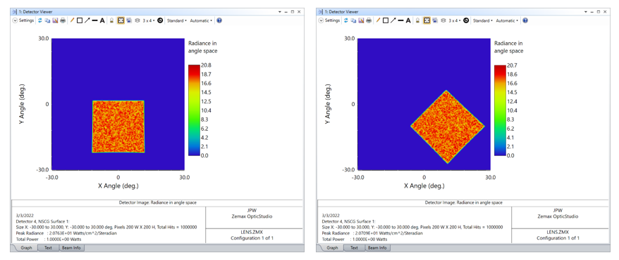
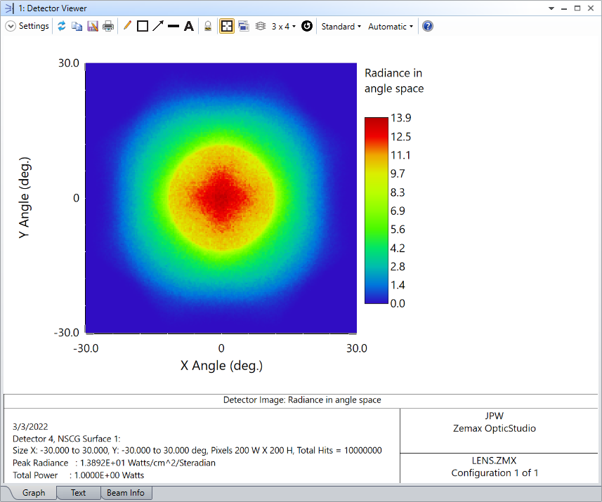
Following up on this, I'm attaching an example similar to one we use in the Illumination and Stray Light course. It takes a circular beam from a Source Gaussian and reflects from an optimized Extended Polynomial to produce a good square distribution at a detector. If you look at the cross sections in X and Y you can see that they are very good in terms of flatness and of a sharp drop at the edges. The merit function, though, you can see is very long, and I built it using the Bitmap Optimization Wizard. This tool allows you to use a bitmap image target to shape the beam into, theoretically, as complex a pattern as you wish so long as you have enough of the right parameters to vary. In this case, it took six variables of the extended polynomial going out to the 27th term (They are X0Y2, X2Y0, X0Y4, X4Y0, X0Y6, X6Y0), but more complicated patterns will need more terms and possibly other surfaces. The Bitmap Wizard is, however, available for Premium licenses only. If you don't hold a Premium license but are interested in this, let us know, and we can put you in touch with your account manager to discuss how to get you access.

Hi Both


Thank you.  helpful articles.


I do have access to premium version, and is trying out the MakeSquare file. I assume with the square.bmp image file, I can optimize to a rectangular flat top distribution, as long as I have enough parameters to vary?  (or do I need to create a rectangular bitmap image file?)


Thanks again.

Userlevel 4
Badge +1

You will want to use a rectangular bitmap. The system is trying to optimize variables such that the pattern at your detector is the same as the input pattern. You then need to choose variables to vary. For the square, the symmetry allowed just those six, the ones entirely in X or entirely in Y. I don't know if that will work for a rectangle or not, as I haven't tried it. I think there's a pretty good chance it will work, though the X and Y coefficients will not match each other in that case and you might need to go to higher orders and let it run a while. (If the local optimizer stops, try using the Hammer and letting it run overnight or over the weekend.)

I created a rect image file.  Thanks.

Was able to optimize to a rect flat top.  thanks.

Hi Kevin,


I try circle target with Bitmap optimization based on your setup and it works. I also try to do the same target optimization with x position offset of detector and it works too but need Hammer optimization for tens hours computation time.


Now I am trying to use ext. poly lens object to perform similar optimization.


Are there other surface type can perform the similar functions?


thanks


Kevin Wang


Userlevel 6
Badge +2

Hello Kevin


I think you could also try the Biconic Zernike lens. Zernike surfaces can be used also for this kind of optimization.


Sandrine


Badge

Is it possible to optimize the parameters of a scatter function to do something like this in transmission?


Dave Kappel

Userlevel 7
Badge +3

Hi Dave,

Just by coincidence, I recently needed a scattering function to produce a rectangular distribution.  Couldn’t see any way to use the built-in functions, so I wrote a DLL which is attached.  It’s a modification of the Gaussian-XY sample DLL.  The transmission parameter is simply a scaling factor applied to each individual scattered ray.  The half-widths are in direction-cosine space as projected onto a plane tangent to the scattering surface.  It may be what you are looking for…

Regards,

Jeff


Badge

Jeff, 


Thanks! That works great!


Dave

Badge

Follow-on question. I would expect that if I put two identical diffusers of this type one after the other, I would get roughly twice the pattern as a single one. But I don’t see that. Am I missing something?

Userlevel 7
Badge +3

It’s a little more complicated than that.  If you look at a single scattering surface using the test model above with a source ray input, and change the angle of the source ray you see that the scattering pattern shifts and/or rotates because the scattering distribution is oriented with respect to the incident ray.  For example, here are two square scattering distributions, one with the source ray tilted by 10 deg. about the x-axis and a second with an additional tilt of 10 deg. about the y-axis included:

Now, if you put two scattering surfaces with this square distribution very close to one another, each scattered ray from the first surface produces a corresponding shifted/rotated pattern, so the net result looks like this (for a normally incident source ray):


Note that if the scattering pattern from one surface only incurred a translational shift, then the composite pattern for two closely spaced surfaces would be given by the 2D autocorrelation of the pattern from the first surface.  However, the fact that the initial pattern rotates as well as shifts creates a more complicated result.


Badge

Thanks, that makes perfect sense. 

Userlevel 3
Badge

Hi Dave,

Just by coincidence, I recently needed a scattering function to produce a rectangular distribution.  Couldn’t see any way to use the built-in functions, so I wrote a DLL which is attached.  It’s a modification of the Gaussian-XY sample DLL.  The transmission parameter is simply a scaling factor applied to each individual scattered ray.  The half-widths are in direction-cosine space as projected onto a plane tangent to the scattering surface.  It may be what you are looking for…

Regards,

Jeff


Dear Sir,

When I am using this Rectangular DLL for “source gaussian” this DLL is not working well. Is this DLL defined only for the “Source Ray”?

Regards,

Chandan Maurya

Userlevel 7
Badge +3

The DLL generates scattered rays taken from a rectangular distribution in angle space.  This distribution is centered about the direction of each incident ray.  So it works best for a collimated beam having all of the incident rays parallel to one another.  If the incident beam contains an angular spread of rays, then the net result will be more complicated as discussed above.


Userlevel 3
Badge

The DLL generates scattered rays taken from a rectangular distribution in angle space.  This distribution is centered about the direction of each incident ray.  So it works best for a collimated beam having all of the incident rays parallel to one another.  If the incident beam contains an angular spread of rays, then the net result will be more complicated as discussed above.


Thanks Sir for clarification, 

Now I have used a collimator lens to coliimate light before using scattering element, it is working now.

One question still I am having,

If I want to impliment this type of scattering behaviour on 2nd surface or exit surface (let light is incidenting from left), of a glass plate then how can I do that? In what fashion I have to give the scattering pattern on glass plate so that it can do the same thing that we have done in simulation using user defined DLL scattering file that you have attached above.

Regards,

Chandan Maurya

Userlevel 3
Badge

The DLL generates scattered rays taken from a rectangular distribution in angle space.  This distribution is centered about the direction of each incident ray.  So it works best for a collimated beam having all of the incident rays parallel to one another.  If the incident beam contains an angular spread of rays, then the net result will be more complicated as discussed above.


Thanks Sir for clarification, 

Now I have used a collimator lens to coliimate light before using scattering element, it is working now.

One question still I am having,

In practial case, how we can give this type of scattering distribution?

Regards,

Chandan Maurya

Userlevel 7
Badge +3

@Chandan.Maurya  For collimated laser beam applications, there are various companies that can make DOEs to generate specific far-field diffraction/scatter patterns.  For example, here are some examples from HoloEye:


Another company that makes light-shaping elements is Luminit.

Reply