Physical Optics Propagation (POP) uses two types of propagation.
This post explains the principles of Angular Propagation.

 +1
+1Physical Optics Propagation (POP) uses two types of propagation.
This post explains the principles of Angular Propagation.
Best answer by Takashi Matsumoto
The Angular Spectrum Propagation is considering the propagation of plane wave. When we think the emission surface at z=0 and detector surface at z=Z and we know the complex amplitude of electricity on the emission surface, the theory gives the complex amplitude of electricity on the detector surface. (Fig1)

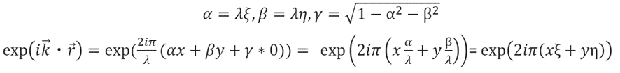
A plane wave of any k-vector can be represented by the following equation using direction cosines α, β, γ and position vector r.

This is the plane wave propagation equation.
The α, β, and γ in this equation represent the directional cosines of x, y, and z. The relationship is as follows.(Fig2)

Now we define Fourier transform and inverse Fourier transform as bellow.

The following transformations are performed on the plane wave equation.
Now the function obtained by Fourier transforming the electric field at z=0 is defined as G(ξ,η,0).
And the equation for E is formed as bellow.

The physical meaning of this equation is that the electric field at z=0 is the set at z=0 of plane waves in various directions with a spectral distribution, G(ξ,η,0), represented by countless α and β.So this theory is called “Angular Spectrum”.
Similarly, E(x,y,Z) can be considered as the Fourier inverse transform of G(ξ,η;Z).

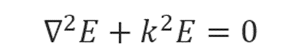
The electric field follows the Helmholtz equation in a space that is not a light source.
Ignoring the integral sign, the electric field equation gives the first term in this equation can be calculated as bellow.
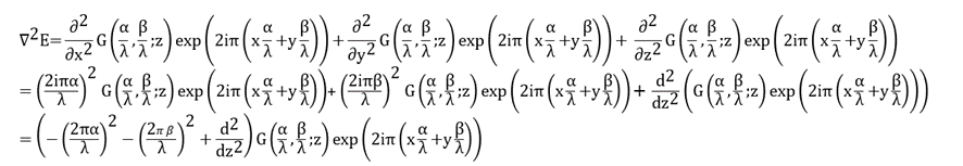
The second term in this equation can be calculated as bellow.
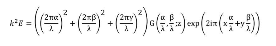
In conclusion, the following equation holds.
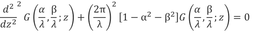
The basic solution to this differential equation is as bellow.

Now making the approximation that the plane wave propagates at a small angle with respect to the Z axis, γ can be rewritten as bellow.
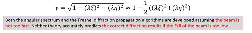
Then the equation can be rewritten as below.

The first term of this equation (exp(i2πz/λ)) represents the incremental phase of the entire surface. In the present calculation, we do not want to know the absolute phase of the entire surface, but rather the relative distribution of the complex amplitude of the electric field. Therefore, this term can be ignored. We further organize the equation.


Finally, the inverse Fourier transform of this G is the E(x,y,z) we seek.
The following is defined as the PTP (Plan to Plan) operator.
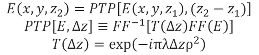
Note that the transfer function T(Δz) has unity amplitude but a complex phase. This phase varies slowly from point to point in the frequency domain representation G if λΔzρ2 is small. But if λΔzρ2 grows large, the phase variations become increasingly rapid. If the phase changes by more than about π/2 between adjacent points in the finite array, the phase becomes ambiguous, and a phenomenon known as aliasing occurs.
For this reason, the angular spectrum method works very well if the propagation distances are fairly short or if the beam is nearly collimated.
When using the angular spectrum propagator, the phase of the electric field is measured relative to a plane. Positive phase indicates the wavefront is advanced along the local +z axis relative to the plane, regardless of the direction of propagation.
A good rule of thumb to use is that if the beam does not change size significantly, the angular spectrum propagator may be used. To propagate beams with small Fresnel numbers, where the beam will change size significantly, requires a separate theoretical and numerical method.
Enter your E-mail address. We'll send you an e-mail with instructions to reset your password.
Do not provide any information or data that is restricted by applicable law, including by the People’s Republic of China’s Cybersecurity and Data Security Laws ( e.g., Important Data, National Core Data, etc.).
不要提供任何受适用法律,包括中华人民共和国的网络安全和数据安全法限制的信息或数据(如重要数据、国家核心数据等)。