Solved

Does anyone understand how to define fields for tolerancing asymmetric systems?


Userlevel 1
Badge +1

From the help files:

XY-Symmetric: Similar to Y-Symmetric, except there are 9 field points used. The 5 Y-Symmetric points are used, and -1.0, -0.7, +0.7, and +1.0 are added in the X axis direction only.

It is also highly recommended when tolerancing non rotationally symmetric lenses...that user defined fields be used.


Are both negative and positive field points really needed along both x and y axes if your asymmetry is only about one axis?  If you designed the system with only positive x field points, for instance, you still need to tolerance it with both negative and positive x field points?


In addition to asymmetry, what if you have distortion?  Aren’t edge and corner points needed as well then?  


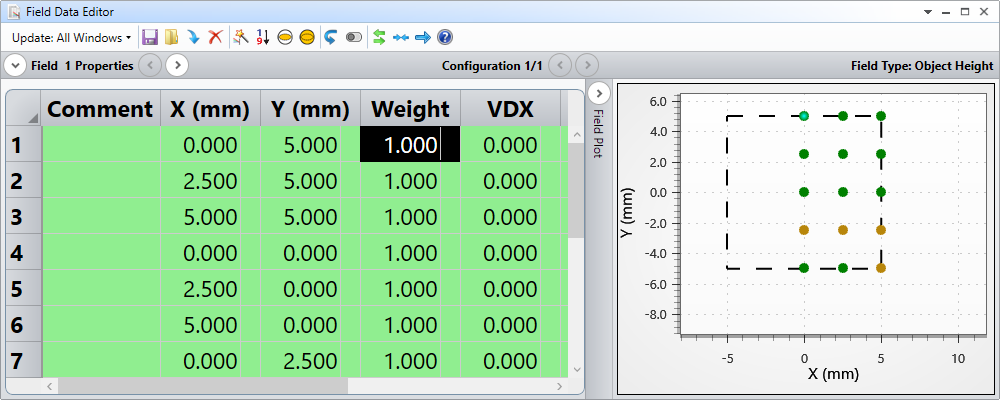
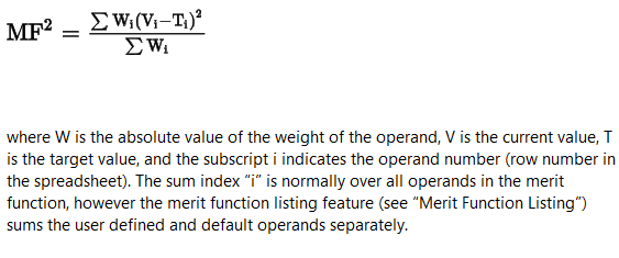
The XY Symmetric option assigns a weight of 4 to the on-axis field.  Can anyone explain the basis of this weighting?  How does that weighting need to be adjusted if more than 9 fields are used or if some don’t lie on either axis (user-defined fields)?


Thanks!

icon

Best answer by Mark.Nicholson 9 May 2022, 23:09

View original

14 replies

Userlevel 7
Badge +3

Hi Donna,

If your system is already asymmetric then I’m not sure you need to do anything. The key thing is to remember that when you tolerance, you add tilts and decenters to the elements in your system.

IF your nominal system is rotationally symmetric then that adds a bunch of stuff that your nominal system did not need to consider. For the nominal system, +y,-y,+x and -x are the same thing. Once it is not rotationally symmetric, they are no longer the same thing.

Think cartefully about your asymmetric system. Is there any implicit assumption of symmetry? A cylinder lens will still assume +/- y can be swapped, even if you can’t swap them with +/-x. Once you tilt the cylinderical surafce, you will lose the half-symmetry.

Now the reason for the weighting...lets say you had three field points at 0, .7 and 1 field, each with a weight of one. Think about the nominal, untoleranced system. If you add field points at -.7 and -1, you will overcound the edgge of the off-axis fields, so you need to incresae the weight on the on-axis to 2 for it to have the smae contribution the the RMS perfromance. Add -1,, -.7, +.7 and +1 in x as well, and you will need to incresae the weight on the on-axis by 4.

Intelligent choice if the field points and their weighting is important to keeping the calculation time as short as possible, as well as keeping the balance of on and off-axis systems. If you can post more details about your system, I may be able to advise you better.

  • Mark
Userlevel 1
Badge +1

Hi Mark,

Thanks so much for your thoughts on this.

Sorry if I’m missing the obvious, but it seems statistically redundant to me to populate both the fields and the tolerances with +/- x and +/- y values.  I haven’t tested this out, but I would propose that if you have both positive and negative x and y values for your tolerances, you should be able to use a quadrant of fields in an equally-spaced grid to tolerance an asymmetric system.  If true, it seems that would provide much more uniform sampling (assuming Zemax is only tracing those user-defined fields), but the weighting is still not clear to me.  If you duplicated that quadrant, rotating it 90 deg three times to create the full FOV, the points lying on the x and y axes (except the origin) would be overcounted by a factor of 2x and the origin would be overcounted by a factor of 4x. 

Aside from that, how do you adjust the weighting if you need (I assume) corner field points to account for distortion?  I suppose to keep this simple, you would use the same number of field points along the diagonals and increase the on-axis field weighting to 8?  That’s a lot of fields.  So, what if you just added corner points and not these additional points between the corners and origin?  Perhaps that wouldn’t give the right statistics in the end?

Thanks,

Donna

Userlevel 7
Badge +3

You got it right Donna. The default Y and XY-symmetric field options just get you started, and they’re fine for a nominal system that is rotationally symmetric. You can also orient the tolerances such that you make best use of the field points you have.

The key thing to realize is that the tolernaced system will be non-rotationally symmetric, even if the nominal system is ritationally symmetric. Since your system is non-rotational to begin with, the tolerances may not require the field sampling to be changed. Or it might...a nominal system with a cylinder lens may use cylindrical symmetry which will also be lost when you tolerance.

It sounds like you’ve got this one understood, so just use User-Defined fields and build whatever field points you need to correctly sample the system. Remember though that they might oversample the nominal system, which has no tilts and decenters.

On the distortion point, distortion doesn’t always maximize at the edges (though it often does) so it’s hard to generalize. The question I ask is ‘how will you measure this in the test bench, or in use?’. Then, try to come up with a way to represent your real measurement to the merit function.

  • Mark


Userlevel 1
Badge +1

Thanks for your additional thoughts!  It would be great if one of the engineers could work out an example (KB article) for an asymmetric system, such as a Scheimpflug or anamorphic design, since there’s no specific guidance for defining fields to tolerance asymmetric systems.  I’ve attached a simple asymmetric example file that could be used.

Thanks,

Donna

Userlevel 7
Badge +3

Hi again,

In this file, you are still exploiting left-right symmetry:

which is fine, because all the tilts in the nominal system are in y. The question is, when you tolerance it, will your additional tilts and decenters break left-right symmetry? If so, you need to define the field points on the left of the object, and increase the weight on the on-axis field point to 2 to account for the double-counting in the nominal system.

I always recommend building some Monte Carlo files are the start of a tolerance analysis so that you can check that everything is behaving as you expect.

Userlevel 1
Badge +1

Hi Mark,

If I define the entire FOV with equidistant field points for tolerancing, why is it that I would need to increase the weight by 2x on the origin point?  Is Zemax doing something other than tracing these exact field points?

Thanks,

Donna

Userlevel 7
Badge +3

No, it always just does as it’s told 😀This is really about computing the RMS performance across field in the merit function and RMS plots.

The problem is that your nominal system has left-right symmetry, but the toleranced one doesn’t. So you need only +x field points say, and +/- y for the nominal.

If you add the -x field points as well, then the RMS of spot, wavelength, whatever will include identical +/- x performance, and the RMS will undercount the on-axis field as it only appears once, but all other field points appear with + and - x symmetry. So, the RMS {whatever} calculation will be weighted against the on-axis performance. Setting its weight to 2 accounts for the existence of two identical field points for all the off-axis fields.

Does that help? - Mark

Userlevel 1
Badge +1

Do you mean RSS over field?  Maybe it would help me to see how Zemax is computing this (in general).

Userlevel 7
Badge +3

Hey Donna,

I wasn’t able to reply as the forum was down for a while there. 

This comes down to what you want to measure in the merit function. If you are using the Optimization Wizard to create the MF, it will compute whatever parameter you choose over the currently defined fields and wavelengths. So for RMS Spot Radius you will get the RMS of the spot size averaged across the currently defined fields and wavelength, with each field and wavelength pair weighted by the weighing you give each point in the Wavelength and Field Editors. 

If you are not using the Optimization Wizrad to build the Tolerance Criterion (which is the ‘User Defined MF’ option) then you have to build the weights for each measurement yourself. Imagine you wanted to tolerance on MTFA at a specific frequency, averaged over fields and wavelength. You could put a bunch of MTFA (lambda, field) operands in the Merit function, and OS will compute the MF as

Does this help? Or make it worse? 😁

  • Mark
Userlevel 1
Badge +1

Thanks!  I appreciate the additional explanation, but TBH, I still don’t have a clear grasp as to why a 2x weighting on the (0,0) field point is needed if equal area-spaced fields cover the entire FOV.  

Userlevel 7
Badge +3

It’s not. The 2x thing is just for rotationally symmetric systems, where performance in the nominal is along +y only. When you go to +/- y symmetric field every field point is duplicated except the center of the field and we increase its weight x2 to compensate.

Just ignore that if it’s not relevant to you.

Userlevel 1
Badge +1

Just to get final clarification, in the example above, you said, “ you need to define the field points on the left of the object, AND increase the weight on the on-axis field point to 2 to account for the double-counting in the nominal system.”.  Are you saying that’s not correct, that if field points are equispaced and fill the entire FOV, there’s no need to assign a 2x weight to the on-axis field point?  Thx!

Userlevel 7
Badge +3

I think that if your original field points scan the whole field of view then you’re good. The Y and XY-symmetric fields pertain to systems that are nominally rotationally symmetric, and so have fields defined along +y only.

Userlevel 1
Badge +1

Thanks for the clarification!


Donna

Reply