I am currently running NSC using Zemax version 2023 R1.00 . I need to check the total power after going through a light guide and the lost energy (errors) due to geometry errors occurring. However, I use the exact same file in another PC with Zemax version 21.2, I got a totally different result.  

With 2023 R1.0 - I obtain 1.66E-2 Watts

With 21.2 - I obtain 6.1158E-2 Watts 

The detector view also gave me different result which confuses me. Is it due to different Zemax version handle geometry error that’s why I am getting different result ? 

How does different Zemax version affecting these differences ? 


Thank you in advance for your help

@Eric.Aw 


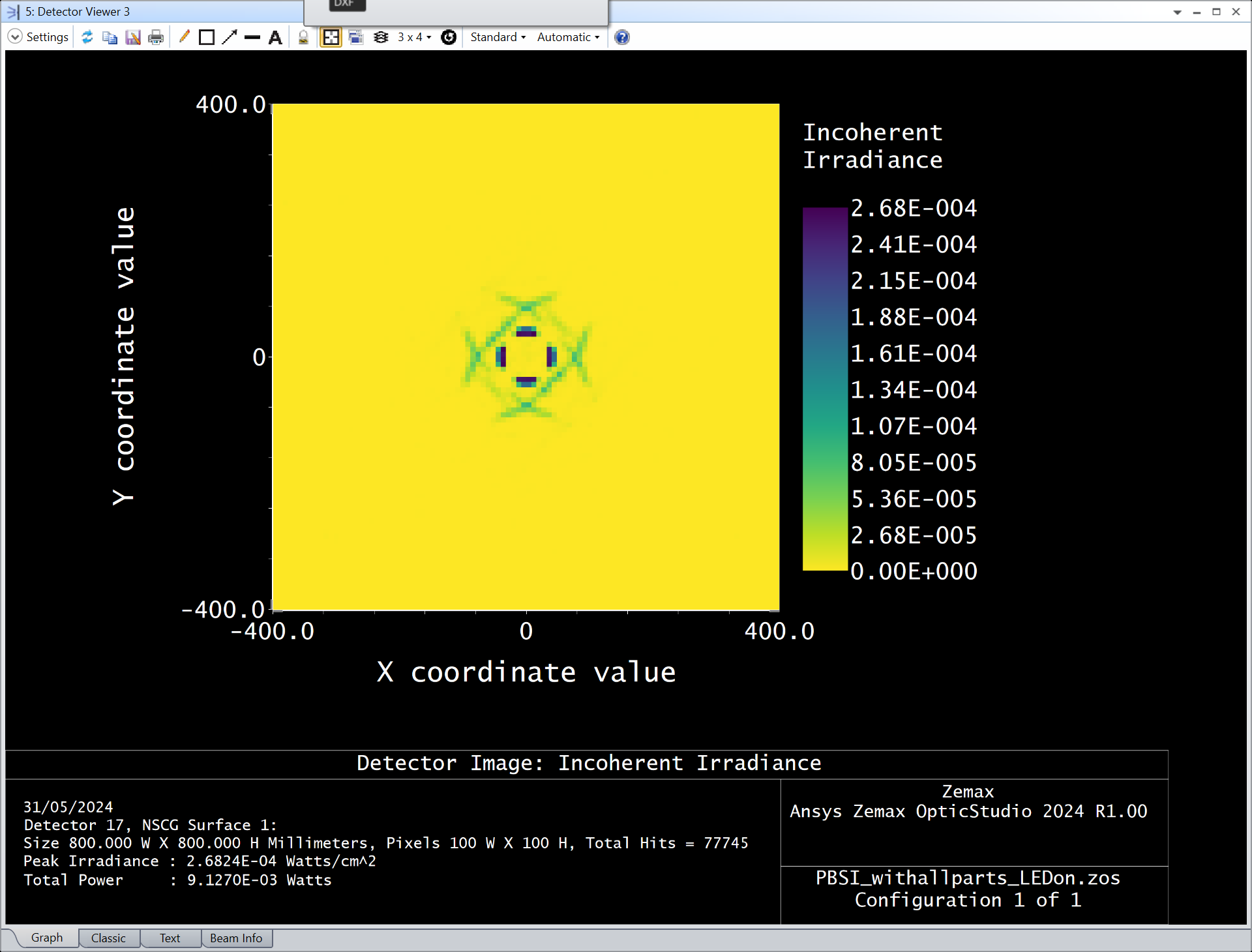
Its quite a complicated file you have there. I think its a sampling issue. You detector has 100 x 100 = 10 000 pixels. For good sampling, there needs to be at the very least 10 rays per pixel (100 000 hits), and even then, your measurement will still be noisy due to the random nature of the ray tracing. If you get 100 rays per pixel, you might start to get more consistent ray traces. And I am talking about rays that make it to the detector. You can read this value from the detector viewer window under the field Total Hits. When I open your archive, there are 3 Detector Viewer, one of them is this one:

The Total Hits is 77 745. This is clearly not enough to get consistent consecutive ray traces. I didn’t test further because the ray trace takes a lot of time and is quite inefficient. You trace 1 million ray per source, but not even 100 000 are detected. You have quite a number of CAD files, have you considered this article?

https://support.zemax.com/hc/en-us/articles/1500005487401-Improving-non-sequential-ray-tracing-speeds-with-nested-and-Boolean-objects

You should try to trace 10 or 100 million rays from your sources and then redo the comparison. If you get 1 million hits and the values are still substantially different, then there is another problem indeed.

I hope this helps and take care,


David


Hi @David.Nguyen 


Thank you for your reply. 

I will look into this nested and boolean webpage . 


I am still trying to identify the issue. 

I tried with just 2 LEDs and the outer housing , both PCs generate the same result . 

Then when I include the “lightguide” CAD file in ray trace process, this issue of different result occurred. 

Any clues on what is the cause of this ? 


Reply